|
How I once again made antennas at home
By Vlada, OK1VPZ, 2020-05-17 / English version edited and commented by Hartmut, DG7YBN
DG7YBN: my first reply was "I do not do DK7ZB designs" (hi). But sure I can design a 28 ohms Yagi with a straight dipole.
Be assured that the bent dipole designs also work for Yagi bays. A good example is the 128 x 11 ele. GTV Yagis at DL7APV and many
smaller arrays used for moon bouncing were every 10th dB counts. But it must be also said that nothing comes for free. Having a second
parameter in the bending angle of the originally introduced by K6STI bent dipole
is a second issue that has to be reproduced on spot.
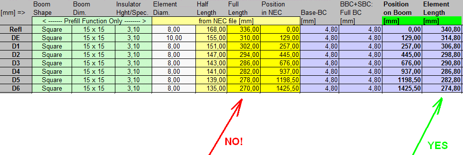
The first design of the final antenna looked like this:
aaaNote: DE means emitter (dipole = Driven Element).
Hartmut sent me a copy of the result of his design in SW EZNEC as well as a comparison of data and analysis of the existing antenna.
Hooray - so I immediately ordered the material according to the yellow column (arrow "NO") of the electrical length of the elements.
After about a week, the elements came and I tried to build such an antenna using the plastic clips of the WiMo antenna.
It didn't work at all! Only then did DG7YBN sensitively warn me that it is necessary to take those lengths with a correction
of 4.8 mm due to the size of the boom and plastic clips. So from the right column. So I had to order the elements
and pay again ... :-)
I built the antenna as soon as the new elements came using the boom and parts of one of the original WIMO antennas
and measured - the first measurement turned out completely wrong. I consulted with Hartmut day after day every step and
sent him measured values, made recommended changes and slowly approached the required
parameters..
I'm not equipped to
measure gain and anteroposterior ratio and I just needed to adjust the antennas well so that they repeatedly have a
reflection attenuation of at least 27dB and in the case of a wet antenna at least 22dB at 432.2MHz, while for a 1dB
change they should be frequency wide min. 3MHz so that they are not extremely sensitive to negligible changes in size
and surroundings. I learned a lot when setting up the antenna. In addition to the length of the dipole, position D2
is probably the most sensitive element. After two weeks of work, I recommended Hartmut to change the dimensions of
the elements as follows (red numbers) with a tolerance of + 0 and minus 0.5mm:
The antenna made in this way (still with the original dipole box and the manufacturer's connector) finally looked
relatively
good, and so it was time to verify the repeatability of the antenna design when making a larger number of them.
(min. 16pcs). Hartmut's answer was to return the position of D1 back to 257 mm (measured from the reflector) and that
the rest, according to his analysis, is not the best, but that it could have been worse ..
Because the original WiMo antennas did not have N connectors that passed
this test and would therefore have to be replaced,
which was a relatively significant financial item, and because drilling the original, relatively weak 15x15 mm boom would
further weaken the strength of the antenna, we decided that we would rather make new antennas than remake existing ones.
First it was necessary to choose the method of dipole production - after good experience from the past, I used the
production of a compact dipole separately and its subsequent installation in a box. From a laminate rod with a diameter
of 10 mm (manufactured as a rod for
electric fences ), I turned the couplings for both halves of the dipole and pressed
them into the inner ends of the radiator so that 18 to 20 mm remained between the ends of the aluminum tube.
The 10x1mm aluminum tubes were both 143mm long. The two halves were joined into a solid unit and I smoothed the burrs
with sandpaper. Subsequently, I drilled about 4mm from the ends of the AL tube with 3mm holes for the dipole screws.
The whole operation can be seen in the pictures:
Another point of the work was the production of a drilling template for the position of individual elements on the boom.
I used a steel U profile of 18 x 18 mm with a wall thickness of 1.2 mm. Because it looked like the WiMo plastic box had
a significant
effect on the antenna fitting, I spent a lot
of time building a suitable box that would be strong enough (we carry these antennas for each contest), waterproof and
electrically least affecting the Yagi. Finally, I proposed to use an aluminum L profile of 50 x 30 x 2 mm, cut to 30 mm slices,
which is be inserted into the box and carries 2 x M4 screws that hold the box to the boom. I think everything
is pretty good to see in the pictures below:
I have now ordered a complete set of
material - at the height of the crisis I used mainly e-shops - such as aluminum
parts (15 x 15 mm boom and individual construction elements, cut to the required dimensions, I bought at the Alupa e-shopu
cut parts came with accuracy up to 1 mm - mostly + 0.5 to + 0.7 mm. I ordered plastic boxes for the
antenna radiator (SCAME type 855)
here - these Italian distribution boxes have waterproof glands that fit a dipole diameter
of 10 mm and have proved very useful to us already during the construction of 12 x 6el. stack that uses antennas
designed by DK7ZB. Well, we bought plastic element insulators for 8 mm elements from
DM3MS .
I made inserts into the boxes from aluminum L profile 50 x 30 mm with a width of 30 mm, which reinforce the boxes and
ground the (important!) N-bushing (see pictures above). Then I assembled the antennas and adjusted them. I have
another job, so it took such a long time, that Hartmut asked if I would be alright. :-) What will you need?
a) A suitable place where the antenna can be directed to the sky and where
there is no obstacle in the area
of ??the assumed radiation angle of the antenna (see simulations). I did this work on the balcony, where
I attached a 20 x 20 x 2 mm square steel tube with a length of about 180 cm to the corner of the railing, into which the
antennas were one-by-one inserted for testing.
b) Without measurement there is no knowledge. A good two meter measurment tape is the basis, a large 310mm drawer is more
than needed. A decent vector reflectometer is a must. But beware: small Mini VNAs, with which the market is flooded nowadays,
must be able to be calibrated accurately, including the measurment coax cable, about 2 to 3 m, which is not always a matter of course.
That's why the elderly
Wiltron Site Master S331 came to honor. But I got on with it myself, when I didn't check the calibration via the
cable quite often and believed that it would be stable. This is not the case, if in April the sun shines for a while and
the measuring instrument with the cable is hot for a while and cold again in a while, it also has a negative effect on
the calibration and
this must be respected in the measurement, otherwise the results will be misleading. It is necessary
to realize that the cable always somehow transforms the impedance (real and complex part) and then the results do not
correspond to reality. So
calibrating the measuring system every half hour is definitely worth it.
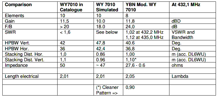
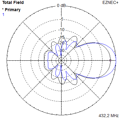
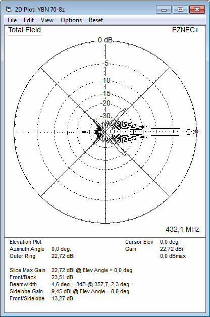
And the results of my optimization? See the link at the end of the article.
Based on a long measurement and "antenna pitching", I finally used the following dimensions for all antennas:
I know it's not exactly the same dimensions recommended by DG7YBN. But Hartmut will comment. We are happy to publish his answer here
DG7YBN: The relatively large SCAME Box and also the offset between dipole and element plane that goes along with using this
box need to be compensated. Usually this is done by trimming D1 in position and / or length alone. But here Vlada went a bit a different route
which I checked in a NEC simulation to be fine also. And we must not forget that using the transformation line made from 35 ohm coax,
as shown in explicite down the page, leads to a need for an impedance of 25 ohms at the dipole. So that a bit further adaption was needed
and well fitted the experimental way by OK1VPZ which he all explains further down on this website.
What should you look out for when adjusting the antennas?
Building real antennas with a low impedance - see DK7ZB's idea of making antennas with an impedance of 28 ohms
- is more complicated in that each piece of free wire at the antenna terminals has some inductance and it behaves
as a more significant shift in complex impedance at a lower real circuit impedance. Therefore, for wiring a 28-ohm Yagis dipole, it is
necessary to have the shortest possible terminals - resp. just such leads as are needed to compensate for the imaginary
part of the impedance. I think it's impossible to hit right wiring here "spot on" without testing.
With the antenna according to this article, it is necessary to pay attention to the length of the elements, their distance
and symmetry (so that the element is the same length on both sides of the boom). If we follow these dimensions with
submillimeter accuracy, there is no need to worry that the antenna will not work in the band. If the elements need
to be shortened, pay attention to the perpendicularity of the cut. The possible use of plastic seals at the end of
the element has a marginal effect.
Much more critical is the case with radiators: the use of a 35-ohm Teflon cable
RG141 (can be purchased in the RF Microwave
e-shop ) has a length of 1/4 lambda with a braid length of just 12 cm
( between the ends of the braid).
If the cable is shorter, the reflection attenuation will be low - for example,
at 118mm length, the reflection attenuation will be 17 dB only. If it is longer, the minimum reflection attenuation
will break into two minima, which will broaden in frequency the more excess length the cable shows. It is the same with the inductance
of the terminals at the antenna dipole. This course
of reflection attenuation indicates that the inductance of the terminals
at the dipole is too small and it is appropriate to increase it - for example, by bending the wires away from the dipole
and this course shows the opposite.
Of course - these are extremes - however, I recommend first setting up multiple radiators
in one antenna and finding the optimization for each radiator individually by the length of the terminal at the dipole
(or by shaping them). It turned out to me that with the length of the terminals listed here, I get the optimal fit
if a small, narrow faston is inserted
on the solder lug on the side of the dipole where the shield is connected
- see the picture here - and only then check the reflection attenuation at placing the radiator in "its"
respective antenna mechanism.
DG7YBN: For the 70 cm band element cutting accuracy within 0.5 mm becomes a necessity. That of coarse pends on the design, but
as a rule of thumb that is a figure. It is no overdoing to buy and make plenty use of a large caliper gauge when cutting elements for
432 MHz Yagis. Wires inside the dipole box should in general be led, as good we can make them, in parallel to the dipoles arms
and only be bent towards the feed line for the least possible length. The following photos of Ok1VPZ's wiring
in the SCAME box are a good example how to get there.
If you set only one antenna (or make a change for all antennas), then within small limits, the frequency responce of a Yagi
can be increased by moving D2 forward by a few millimeters. Shifting D2 is critical! However, the
frequency response of the antenna is especially related to the length of the dipole. Interestingly, the length and
position of the reflector has little effect only and the position and length D1 has a strong effect on the impedance
of the Yagi. However, if the inductance of the terminals of the low impedance dipole is too low, it can be somewhat
compensated by a displacement in forward direction. This is also the reason why the test antenna with high terminal inductance gave
me a position of 266 mm instead of the correct 257 mm. By the way - this may be related to this whole "adjustment", because
the calculation is made for an impedance of 28 ohms and the transformation cable is 35 ohms - the output
impedance using this coax should ideally be less than 44 ohms. In oreder to "tune" to 50 ohms it is necessary to introduce additional correction
elements into the circuit - which are the parasitic inductances and capacitances. It follows that the older circuit
solution mentioned here
make a deep sense for antenna repeatability and consistency of antenna parameters (which is
important for antenna assemblies) with low emitter output impedance - only the AD450 laminate is unfortunately
no longer available ...
I will look for another solution to ensure full repeatability as of such a microstrip matching circuit.
However - to make matters even more complex: part of the production of these antennas was the need to address their construction resistance to rain.
I liked the WiMo solution. They fill the radiator box with polyurethane (PUR) foam used for construction works. It is full of bubbles after
hardening and thus its dielectric constant will be low. It also reliably clogs all leaks and is water-repellent.
So I was tempted to use a PUR foam to seal the matching circuit of a SCAME box also, which in this use has one unused "port", i.e. a sealant
filler plug. So I filled the ready made antennas with foam. - Make sure the pressure in the foam spray can doesn't tear the seal in this
filler plug, hi. With the foam solidified (2 days), I measured the antennas again. For antennas with a reflection attenuation of
25 to 29 dB, the adaptation has improved by 2 - 3 dB. On the contrary, for antennas with super adaptation (37 dB and better) there
was a certain splitting of one minimum to two. However, there was no significant deterioration in reflection attenuation to be observed.
From the logical point of view - even if the foam is "thin" inside the box we find a certain reduction in the coefficient of propagation speed
and thus a relative "elongation" of the line respecitvely of the inductance at the dipole wiring. In practice, this should have
no effect. Only I was nicely
"tangled" after the foaming of the antenna boxes ...
Not the last task was to determine the sensitivity of the antennas to detuning by rain. I used a common
water sprayer
for moistening houseplants. I have not tested all the antennas, only 30 percent of them. The best frequency response of the antenna
drops by about 2 MHz, but for all tested antennas a limit of 21 dB reflection attenuation remains. I would consider
that satisfactory. See pictures.
Conclusion: in addition to the above, I experimented a lot with measuring the radiator alone without incorporation
into the waveguiding structure of the antenna using a pocketVNA. If you are interested in the lot of results, it is possible
to download them
here. But I say in advance that I did not read anything reasonable from those measurements. I measured
the dipoles like shown
here, but if you would like to correlate the results of the table with the final results of the antennas,
I would like to point out in advance that the measurement of dipoles took place before the optimization of the inductance
of the dipole connection. This is not to say that there is no correlation, I just don't see it. I still have a lot of work
to do to complete the antennas (dividers, cables, holders ...) and the day is not endless. In any case, it would be worth
paying even more attention to microstrip matching to ensure 100 percent repeatability of the design.
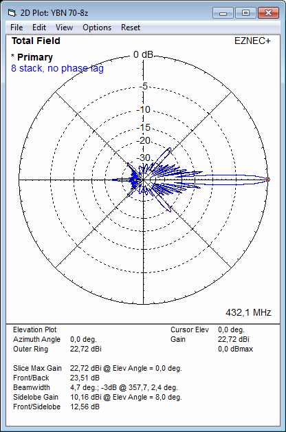
DG7YBN: ok, lets calculate an expected maximum phase difference between the Yagis and simulate the impact in an 8 Yagi stack.
The matching coax is a quarterwave line of a length of 120 mm. That equals 90 deg. of phase. Lets assume a maximum cutting
and soldering tolerance of +/- 4 mm. If 120 mm equals 90 deg., then 4 mm equals 3 deg. of phase.
My conclusion: Neither gain nor F/B are influenced. Pattern shape is touched marginal by the simulated maximum phase lag
that could occure due to wiring the dipole boxes in slightly varying length of coax or split ends of coax.
Well, for a last word: if you are interested in the measured results of reflection attenuation
of all antennas, then here is the table:
Measurement conditions: Wiltron Site Master S331. The VNA was calibrated to the end of approx. 3m
of cable (to the antenna connector) at 432.2 MHz in the location were the measurements took place.
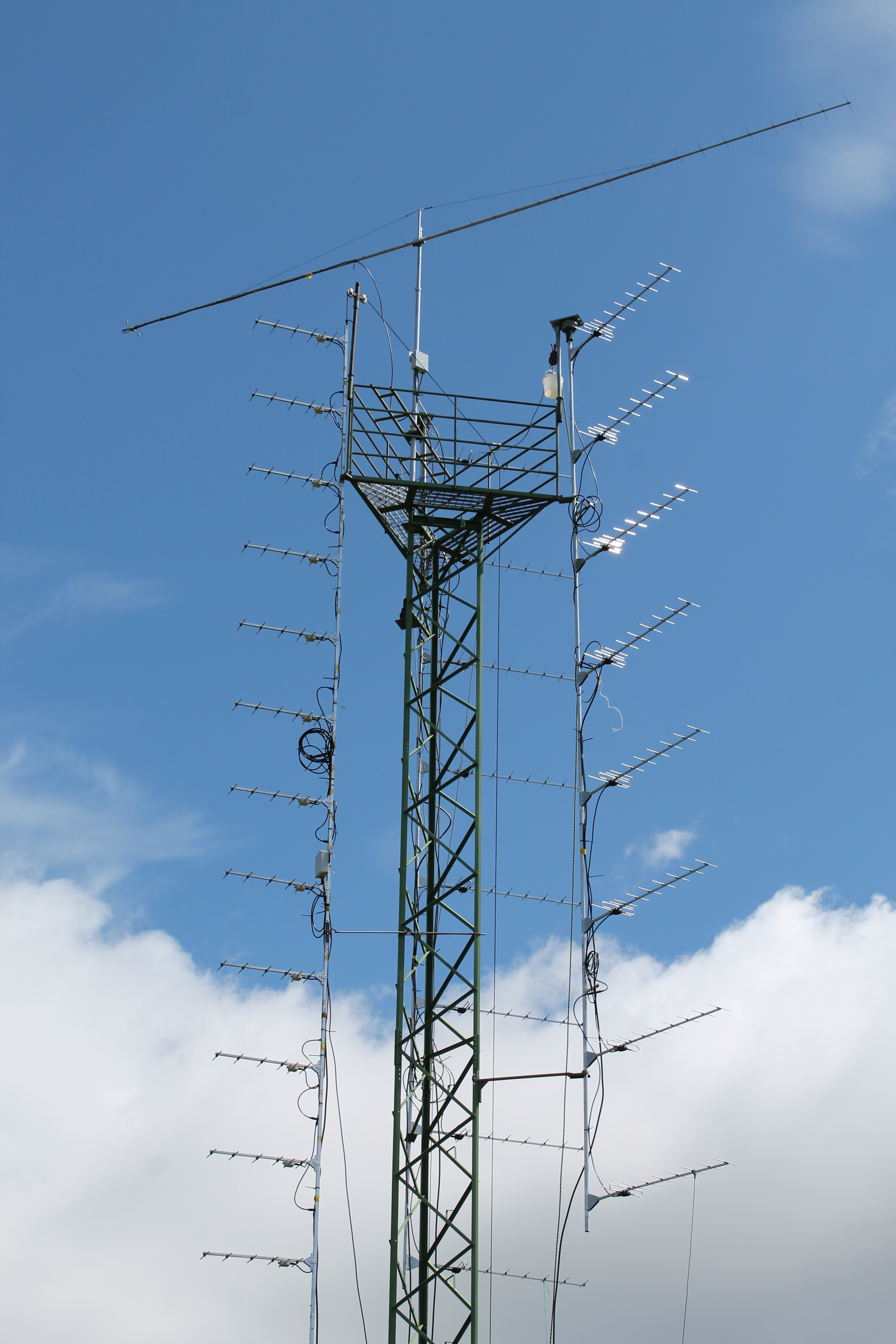
73! and hear you on 70cm during the July 2020 Contest. Perhaps (but it remains to be seen) already on the new DG7YBN antennas stacks
|
|||||||||||||||||||||||||||||||||||||||||||||||||||||||||||||||||||||||||||||||||||||||||||||||||||||||||||||||||||||||||||||||||||||||


