DG7YBN - Low Noise Yagis
Measuring Antennas
(x)
Plotting Antenna VSWR right
Last Update April 13th 2024How to setup antennas for reliable VSWR or Return Loss plots
This is how I plot my 70 cm Yagis for the quick reference in my yard. For the full reference I pack everything into my car and drive to a flat hill top plateu with no houses or trees around for a couple of 100 meters.
But anyway, a configuration as shown in the sketch below will do for very most applications unless we want to define new BC numbers or similar.
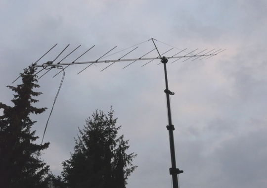
Minimum Setup for plotting a 70 cm Yagis VSWR

1. Make sure not to get hit by a falling down antenna or pole (!). Loose masts and poles are a potiental source of danger. Do not set up a loose pole near high voltage lines or where people might get hurt.
2. Get the main beam lifted from touching gnd or anything else in range of approx. next 20 meters by tilting the pole. Which is in accordance with what DL6WU says about measuring VHF / UHF Yagis.
3. Let the coax drop down in wide loop. This is about not producing anything close to an odd multiple of 1/4 lambda loop against boom or pole ... which might interfere with SWR etc. It is a good idea to try different fixing position for feed coax if antenna seems to misbehave and see if that does anything to the SWR.
The old school saying: Near Field and thus reactions to environment would end at 1 lambda or so from the antenna might be true for dipoles, NOT for long Yagis though. With the test antenna builds of YU7EF designs for WiMo one could trace or detect cars or even pedestrians walking by in 30 m distance on the VNA plot line (!). Find more read on this in next chapter.
And producing a REAL Return Loss plot
by tilting a Longyagi for 144 MHz with right equipment
A GTV 2-14w built by Jörg, DL2VL and tilted by ~ 30 degrees on a crank mast in sufficient height.
This is exactly the way to achieve a proper Return Loss plot. Yes, I know ... such equipment is not accessible by everyone. But as phyiscs are that way there is no escape unless relying on well built up know how paired with experience maybe.
Image Source: Photos and build by Jörg, DL2VL

Where does the Far Field Region start for a Long Yagi?
From my article "Applied Conversion of Segmented Wires from NEC2 to 144/432 MHz Yagi Elements - Part 3", Dubus 2/2011 & Dubus Technik XI
"Most Radio Amateurs do understand the Near Field Region where the Antennas impedance will be influenced by the environment as 2 times the wavelength from a Dipole. Citing typical Amateur Radio Lecture Websites show the following: The Near Filed reaches out a half to maximum one wavelength around the antenna. That might be true for Isotropic Radiators, Dipoles and alike but certainly not for highly directive antennas. Sadly that statement has become a conventional wisdom that is falsely applied on all kinds of antennas in Amateur Radio circles. If we want to measure Long Yagis correctly we need to get a revised picture of where the Far Field Region of our actual build will begin. In order to achieve a true Return Loss measurement we must stay clear of Near Field and Fresnell Region at least for the main beam.
The Radar Theory shows an equation to calculate the end of influences i.e. start of Far Field region that delivers much larger values. Taking an example wise 6.0 m long Yagi for the 2 m Band we derive at the following figure:
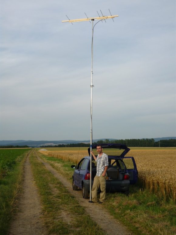
Verifying results on a wide open flat hill top
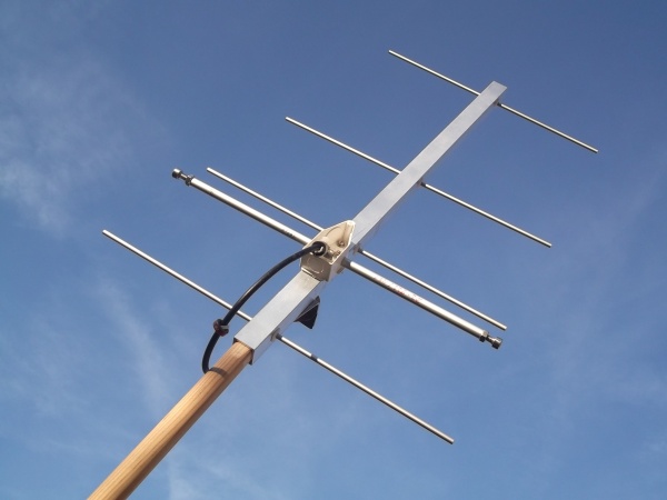
For whatever real reference measurement we need an area with nothing disturbing the antennas Near Field and Fresnel-Region. The photo shows the author with a 2 m band YBN 2-5 on wooden lace as boom on his 'home hill'. Note the distance to trees in the background. Exact measurment of antennas inbetween houses and trees does only work to a limited extent on VHF.
Analyser and Laptop are hung up an on a 12 VDC to 230VAC converter for camping
How to set up a Measurement Yagi the right way?
This paragraph is about essential understanding of fundamental working prinples of the Yagi-Uda. Without you might get lost in false assumptions when tuning your homebrew Yagi antenna.
The Driven Element (DE) or Dipole is subject to influence of mounting plate or box and boom correction in case of being mounted narrow above boom. But probably most of all the connection to the feeding coax being imperfect by means of split up length to connect core and shield.
Fig. A1 shows the 'as best as we get it' condition. Shortest split ends and the right portion of BC or Box compensation applied.
Fig. A2 shows how we should deal with pigtail lengths if only we knew the factor i.e. exact compensating span width prior to testing.
Fig. A3 is very common but worst scenario. Why so? We leave the DE too long because cutting is easier done than prolonging it later on. Second the coax is connected without caring for the split length and what a few millimeter mean on the designated VHF/UHF band.
Now, why is the above so important?
Actually it is not that important, as many a proven builds done without that care working out there show. But if you want to achieve the best and true pattern all has to be fitting. So read on please.
Below we find sketch A4 of a Yagi-Uda holding two envelope lines. The inner, black one symbolises an element set with no or not sufficent BC. Whilst the outer, green one resembles a Full BC as regular BC plus added compensation for a models high segmentation density (SBC) in case. For the very most (non special Low Noise) Yagi designs we will find the too long a starting length of the DE in addition to the long pigtails working as 'force that pulls down' the Yagis response frequency. And thus disguises the need for more BC than applied.
So that when not plotted very carefully and judged with experience the VSWR seems alright and the Yagi goes up the pole. But alas, with typically less 2 or 3 mm on all element lengths. With a spoiled pattern as far as max. gain is concerned. It will drop by approximately 0.2 dB and, hurting far more in EME and contest use, F/B and F/R are down by several dB in most cases.
How to get a grip on finding the true length for a DE?
It is recommended to produce adjustable end tips. Which can be done by cutting threads into the tubes used and fit screws with arretation nuts into these.
• A tube 6 x 1 fits a metric thread 5 x 0.8 mm ISO for regular screws M5
• A tube 8 x 1 fits a metric thread 6 x 1 mm ISO for regular screws M6
• A tube 10 x 1 fits a thread 8 x 1.25 mm ISO when the ends are compressed a little
• And finally: another masterpiece out of DL2VL's workshop holding a fine thread with a pitch of 0.5 mm. Thread is 8 x 0.5 mm for which the ideal tapping drill hole should be Ø 7.5 mm. Which he passed by in compressing the slotted end in the turning lathes collet and cutting the thread in there.

Trimming / Tuning Tubes
A Boom Correction may be right or wrong. But as long as we do not get the dipole right in length the BC is overshadowed by influences of the not exactly matching dipole. Typical influences caused by a dipole box or holding plate, length of split end of coax cable etc. must be compensated before we can set off to determine the Boom Correction or judge a Yagis frequency response in the full.
Adding trimming screws to the tips of a dipole is an elaborated way to work this out.
With any piece of sligtly larger in diameter tube we are much faster. A tube on one side usually does the trick. These tubes do not necessarily need to be fitting in diameter. We do not need electrical contact as this is RF in the VHF/UHF region. The tube can be held in place with tiny bits of tape or whatever comes to mind. A useful tube length seems to be anything from 15 ... 25 mm.
How do they work?
A thickened dipole from half way point between boom and tip outwards bound works a bit like a top loading for a shortwave GP. From half way point inwards it works like thickening the element i. e. shortening the dipole by a small amount.

Of coarse we can also apply one or a pair of tuning tubes to D1, often the most critical element:

In case we want a permanent trim we can use tubes of fitting diameter like 8 x 1 mm tube for a 6.0 mm element. By slotting these and giving a press fit with a plyers, when in place, they will stick to the element firmly.

Mind that if we trim for checking on a Boom Correction we do not want the trim to get our Yagi onto the designated frequency on all costs BUT to best Return Loss, no matter what frequency it is. As this will be the true point of frequency the Yagi gives best response on. If that now is not same a the designated frequency we will have to work on the BC value for given boom size and insulators.
• What about many Low Noise or Low Temperature Yagis with reverse influence of dipole length?
The GTV 70-14m for example has a 'negative chamfer'. More explicite, many low noise Yagis have the property to go down in frequency when the dipole becomes or already is shorter then it should be and vice versa. Simply put that is because D1 is higher loaded with current then the dipole is. So this is a reverse behaviour to what one would expect, but the effect is explanable. The fast majority of Low Noise and Low Temperature Yagis by whatever designer shows this behaviour. To find out it takes only one test bit of aluminium stuck to a dipole tip and if the Yagi goes up in frequency the Yagi is of that category.
Detailed Tuning Instructions for Bent Dipole Yagi-Uda Antennas
Antenna feed point impedance Z = R + jX with R as Real Part and jX as the Imaginary Part. While R is the ohmical feed point resistance the jX is of capacitive or inductive nature. For a bent dipole arrangement this simply put means R is transformation ratio to 50 ohms inside the Yagi to antenna terminal. While jX accounts for the length of the dipole in context to the Yagi-Uda structure being too long or short if not zero.
Using a VSWR meter we cannot monitor changes on the individual parts of Z. We do not see R alone nor jX. Thus we access the superposition of both as Z only. And here comes the challenge: As for example Z = 59 + j (-2.8) ohms makes a VSWR of less 1.2 .
When bending and varying the length of the dipole we might be lured into wrong direction by the sum R + jX when tuning the antenna. Which would mean to derive non suitable bending angles which are compensated by also non fitting length of the dipole. The resulting complete band VSWR plot would not resemble the engineered one. Hence I advise to work towards the best VSWR while bending and modifying the dipoles length in iteration steps as follows:
1. Set up dipole pre bent to sketch
2. Measure the VSWR at designated frequency
3. Bent 1/2 inch back (adjust with a tape measure noting distance tips of dipole to reflector)
4. Measure VSWR (better / worse?), note that for direction
5. Add small bit of metal (screw, something) into ends of dipole, extending length by 3..5 mm
6. Measure (better / worse?), note that for direction
7. If worse, cut away 2 mm
8. Measure VSWR
9. Better? Bend a little further into the better direction
11. Still better?
12.Otherwise try same in reverse direction
13. Repeat with / without metal bits extending dipole length
14. If worse, cut away 2 mm
15. If better, play with bending angle for a further round
Once you found direction and all you bend and cut betters the VSWR you have a clear direction and you may proceed without too much back and forth and speed it up.
• Mind
Most Low Noise Yagis or Low Temperature Yagis have the property to go down in frequency when the dipole is shorter then it should be and vice versa. Simply put that is because D1 is higher loaded with current then the dipole is. So this is a reverse behaviour to what one would expect for a common or high gain only Yagi, which is hereby explaned.
• Quick Check methode for dipoles made from sheet metal like the 'Blade Dipole'
Instead of trimming on the dipole arms over and over I do attach a piece of leftover aluminium or roughly double size of a cent to one dipole arm with just enough tape to keep it in place. Moving it from halfway of the dipole arm inward to boom virtually shortens the dipole, positioning it towards the tips prolongs the dipole. So you be much faster without fearing to cut the dipole too short. It will give direction whether the final dipole must be longer / shorter. So you can work on small adjustments on the bending angle easier.
• Reasonable extra length of dipole to start with on 70 cm
Added 20 mm per side for a start is pretty much on 70 cm. For this band in my view is on the edge of being microwaves. 4 or 5 mm per side or so is a better starting base and plenty of headroom for trimming actions on 430+ MHz.
Example: GTV 70-14m. In my simulation with added 5 mm per side the Yagi looks like loosing focus, no clear dip down in VSWR at all, but then you are close. While with added 10 ... 20 mm per side she completely looses focus and drifts to 437 ... 439 MHz with no good VSWR at all. At 1 mm longer per side she makes up her mind and comes to settle at 432.2 MHz with less good VSWR.
At 2 mm too short she still is around 432.4 MHz but again, with no better VSWR then 1.13.
That might give an idea about hsuch Yagis behaviour regarding fast changes of the dipoles length. Within 2 mm +/- she settles around 432.2 but then VSWR can be trimmend to lowest. Always in combination with timy adjustments on the bending angle, step-by-step. This behaviour is of mid to narrow band Yagis, eaxact numbers only apply to the GTV 70-14m. But this may give an idea how in general such Yagis, of which the elements have a reasonable Boom Correction applied, are lengthened and positioned to fitting accuracy, will react.
How to setup a Yagi suitable for measuring a Boom Correction Factor
• What type of Yagi to use?
The Yagi must be one with a decisive peak in Return Loss. USe Return Loss instead of VSWR as the plot curves resolution is much better to see what is happening below ~ VSWR 1:1.5. The Yagi should be one with a straight split dipole.
• The boom
The boom should ideally be a good bit longer then the Yagi to build. So that we have rear and front offsets of some centimeters to give the first and last element the same impact as all the others (that is the reason why I give offsets of 30 ... 40 mm in most building tables).
• First you choose a starting point for a guessed BC. Around +3 mm is a fine for most insulators at 144 MHz and a 20 or 25 mm boom. The existing BC factors for various insulators are a good indicator Pick the one that is most similar to
• How to feed the test-Yagi?
What I found best solution is use a carefullt´y trimmed to 1/4 wl at 144.300 trimmed piece of RG58. Spilt side very short ~7 mm to dipole, far side end into an N-socket with an aluminum bracket to boom. See a photo of such a line as 3 x 1/4 wl in use for 70 cm BC test:
The concept of "grounding" the 1/4 wl stub needs a metal mast clamp and metal pole to put the Yagi to.
Note the multiple ferrite cores. The first one should be placed as close as can to split end at dipole. Much closer as on this photo
Then a length of coax that is far from trying to match 1/2 wl or multipe. In theory this works but ne never gets a 100% 1/2 wl or multipe with N-plugs included. So it is better to be far off that length .. so the 1...2 % mismatch in length do not interfere. Then to be sure the feed coax does no transformation tricks I always do a second plot using a different length of coax or by adding another random length and compare plots.

• Trim screws in Dipole
Dipole and 1/4 wl line form a unit. If line a tiny bit too short the dipole appears too short and vice versa. So we trim this last bit to be very sure to get the BC or say the actual state of best RL at what frq. right. With the screws we can compensate the last bit of possible mismatch of the whole 1/4 wl line and influence of dipole bracket or plastic box and all there is left to compensate.
If you do not manage to cut threads in 10 x 1 mm tube you can use bits of 8 x 1 tube and push them in. Something like that. Anything that makes it adjustable in length.
• Trimming and plotting
Do not trim towards the wanted frequency but to best Return loss, no matter what frequency it is at!
For we do want to find the right BC instead of what we usually do to trim an existing antenna to frequency. So here we want to find the true frequence response of the test-Yagi as it is now to calculate a BC from there on.
73, Hartmut, DG7YBN
Who has been looking at this website?
Overall Counter
