DG7YBN - Low Noise Yagis
DG7YBN
Low Noise Yagis
Low Noise Yagis
DG7YBN
Low Noise Yagis
Low Noise Yagis
Online Calculators
(x)
RF Calculators
Last Update May 1st 2024General Issues
Receiver Sensitivity
Impedance
Links to other Online Calculators on dg7ybn.de
Receiver Sensitivity
Impedance
Links to other Online Calculators on dg7ybn.de
Receiver Sensitivity
Impedance
Links to other Calculators
Frequency to Wavelength
What maths are driving this calculator?
• Wavelength in vacuum: λ = c / Frequency
Speed of Light c = 299 792 458 m/s in vacuum
A Wavelength λ in a medium other then vacuum is described by
• Wavelength λ = (c x Velocity Factor) / Frequency
The Velocity Factor v is a function of
 as relative dielectrical number or Permittivity of a medium.
It describes how fast a wave travels in a medium and thus is directly related to change of length of a wave in that medium.

 (vacuum) = 1.00000 => v = 1.0000
 (air) = 1.00059 => v = 0.9997
Mind that coaxial cables Velocity Factor commonly is given for 1 MHz or so by the manufacturers. Due to a slightly frequency depending
 of the insulation plastic and hence V-Factor at VHF/UHF cables might be shorter
than computed by 4 to 7 percent.
EIRP : Equivalent isotropically radiated power
What is EIRP about?
EIRP is a term often used with the topic of RFI (Radio-Frequency Interference) and Radiation Power of Electromagnetic Fields. Simply put EIRP stands for the equivalent of fed power to an isotropic radiator (gain = 0 dBi per definition) vs. a directional antenna with certain gain over the iso.-radiator and other fed power. By referring to the iso.-radiator directional power levels in beam direction can easily be compared. In Amateur Radio use that could be comparing powers of two stations. Lets assume a DX setup for 432 MHz: one station is feeding 700 W into a 17.1 dBi antenna, the other 400 W into a 19.8 dBi antenna. Which one 'pumps' more radiation power into beam direction?
What maths are driving this calculator?
1. Conversion of Isotropic Gain of Antenna to numeric number


Watts to dBm & dBm to watts Conversion Calculator
dBm is Decibel-milliwatt, it references power to one mW - with 0 dBm = 1 mW
• 0 dBm = 0.001 W
• 10 dBm = 0.01 W
• 50 dBm = 100 W
What maths are driving this calculator?


dB Conversion Calculator
This conversion works with GAIN and LOSSES:
• Gain 3.0 dB = 2.00 numeric
• Gain 0 dB = 1.00 numeric
• Gain -3.0 dB = 0.50 numeric
What maths are driving this calculator?


• 2.00 numeric = we know that 3 dB gain gives double output
• 1.00 numeric = adding 0 dB does not change anything
• 0.50 numeric = is half power out
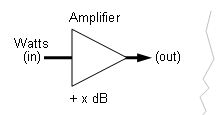
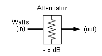
Amplification Gain or Attenuation to Watts in/out Calculator


What maths are driving this calculator?
Power Levels in dB can be summed (gain) or subtracted (loss).
So we convert Power Input in watts to Power Level (dB) refering to 1 watt (dBw)


Note the rather explicite notation 'Loss_x'. This commonly would be another G_x with gain < 1.00


Finally we convert the resulting Power Level (dB) into watts again

Temperature to dB Calculator
What maths are driving this calculator?

And in reverse ... dB to Kelvin Calculator
What maths are driving this calculator?

μV to dBm Calculator
What maths are driving this calculator?


dBm to NF Calculator Receiver Sensitivity to Noise Figure
• BW = Bandwidth
• dBm = Power Level referring to 1 mW
• To = 290 K or 17° C ambient
Using this calculator with Receiver Specs from a Data Sheets
As different S/N levels are used as well as bandwidth depends, look up those specifications
with the μV or dBm number given for sensitivity and enter to calculator form to yield a correct result
Typical numbers
• nominal BW's: CW or as SSB = from 2.4 ...3 kHz, AM = 6 kHz, FM = 12.5 ... 25 kHz
• CW Filter? => acc. filters bandwidth settings
• nominal S/N = 6, 10 or 12 dB
What maths are driving this calculator?
k = Boltzman's constant (1.3 x 10⁻²³ J/K)


SNR to S-Units and μV Calculator
G/T Calculator
What maths are driving this calculator?

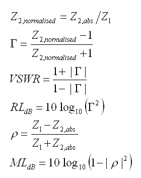
VSWR & Mismatch Loss
Z1 would be Zo or 'at Transmitter or Receiver' while Z2 could be antenna feedpoint impedance
Mismatch Loss (ML) expresses what Losses derive from connecting non similar impedances
Mismatch Loss application example:
Given a 50 ohms feedline coax of 10 m length with a loss of 1.2 dB shall be connected to a 75 ohms antenna. What is the total loss here?
The calculator puts out -0.177 dB for Mismatch Loss, the coax adds 1.2 dB, total loss is 1.377 dB.
What maths are driving this calculator?
Z2 in absolute numbers is


73, Hartmut, DG7YBN


