-
• Main Page
- • Home • Building
-
- Boom CorrectionIntro to Boom Correction and complete Collection of Factors
• DG7YBN semi-insulated on Boom
• DL6WU / G3SEK formulas and charts in detail
• DJ9BV insulated through boom
• I0JXX insulated through boom
• K1FO insulated through boom
• VE7BQH Cushcraft & Cudee on Boom
• Intro to SM5BSZ's BC.exe
• Microwave BC numbers
• Model Segmentation to real world frequency issues
• The BC-Excel Yagi Element Configuration Tool Download - Symm. & BalunsSymmetrising Devices from Sleeve Balun, F9FT Tube, EMI, G0KSC, Pawsey, 50 ohms Quarter Wave Line to 12.5 and 28 ohms DK7ZB Match ... plus Test Equipment - the RF Current Meter
- Phasing & Matching LinesHow to measure coax stub lines, produce coaxial impedance transformation lines, Baluns and how to stack and match with coax lines
- Howto - Bent DEHow to bent a GTV Yagi DE with a simple selfmade tool:
Bending aluminium tubes by hand leads to buckles and brocken tubes. So I show what a simple selfmade tool looks like. You will need just a piece of wood, a few minutes and a jigsaw to produce one.
It will make the job much easier.
DIY - Bending Tool
- Building a YagiA collection of building hints - from DE-Box to bending Support Struts and mounting Elements. - Under Construction -
- Boom StrutsA collection of building hints - Planning and bending Support Struts and making bending tools. - Under Construction -
- Scaling Yagi ElementsHow to scale complet Yagis in Frequency and Element diameters from one dimension to another by hand
- Boom Correction


Preface
Boom Corrections
Dependencies
Preface
Through the transformation into a real low noise pick up, side lobes supressing, yet high gain antenna the development of the Yagi-Uda has made a large progress since about 2005. All due to faster personal computers, better NEC frontends and nec4 kernel initail designs by YU7EF and the follow up designer lot. And a new 'dimension' of measurement accuracy due to affordable antenna analysers. Additionally the reintroduction of low impedance Yagi-Uda structures (not necessarily a low impedant feedpoint, see LFA loop and bent Dipoles) adds more than gain today. But in order to take full benefits of this forward development the call for precise element lengths and positions is more urging then it ever was. Hence Boom Correction (BC) is a serious topic!
Do not build following plans that just state to add 2 mm or give vague information only. You can do better then that. Read carefully and note that all the mentioned BC - factors reflect on a specified way of mounting the elements. Whatever you chose to build and how, the BC must match the forseen way of mounting the elements. If likewise using 'DJ9BV numbers' you have to stick to the mentioned nylon rivets, square boom and 4 mm elements.
To complete the package the way of matching or balancing the feed and the realisation of feedpoint and dipole housing must fit the picture too. Find plenty of additional information on my "Building a Yagi" and "Symmetrising and Baluns" website.
Wishing you happy building of better Yagis! 73, DG7YBN
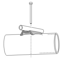
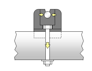
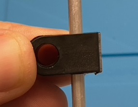
Acryl insulator on photo above is a self machined demonstration piece
Basics: Boom Correction numbers (BC) are given as lengths to be added to the "free" length of the element. As in NEC we simulated without any boom - The BC compensates for the influence of boom and mounting bracket. All the BC numbers below are "add-to-full length". To make this clear: the example shows an ele. of 940.0 mm from NEC geometry, BC is 3.9 mm, total cutting length is 943.9 mm.
Any BC numbers are depending on the actual building style. Basically element mounting styles may be rationed in
In fact we may use more details than enclosed in the Old School approach, such as
In the past we have seen a set of BC numbers that are established now by means of being granted, such as DL6WU and later extended G3SEK / DL6WU. Today we use them unbalanced for whatever Yagi-Design and its models segmentation. Is that feasible when we want a real world Yagi with optimum performance? In case you might wonder why there are no specifications included for using round or square boom? =>
From SM5BSZ website: Traditionally there is [... was...] no difference in correction factor [.. published...] for round or square booms.
In the source code of SM5BSZ's BC.exe we find a line refering to influence of square and round boom shapes. He computes an equivalent boom diameter D by multiplying with a factor of 1.18 for any square boom. So that the equivalent diameter for computing the elements BC is 18% larger for any square boom as for any round boom of same diameter. As all factors given in the BC.exe are based on very carefully executed measurements this relation of 18% might be considered for any other insulated through boom BC as DL6WU/G3SEK, DJ9BV, K1FO etc. as well. Always mind the base (round or square boom) the specific BC was set up with. That is why I have added the settings the BC was produced with to the following list of BCs. Like "applies to square boom, nylon rivets, 4 mm elements and 6 mm hole in boom" in case of DJ9BVs BC.
Another thing that applies to the following original DL6WU/G3SEK formula set is the habit to focus on Correction numbers as fractions of boom diameter in wavelengths. Perhaps as a reverberation of the first methodical papers on Yagi design by P.P. Viezbiecke and others. In straight words - these original formulas do not deliver an element length correction in millimeters right away. Set up by antenna analytics they deliver analytical data on Yagi element behaviour in general. Using the wavelength as reference is a perfect way to express a Boom Correction in a generalised way.
A real pain though, if you want nothing but the needed extension on an actual Yagi you want to build. The terminology and formula symbols B for boom diameter, C for Correction and C/B as their fraction as numbers in wavelength might look misleading if you do not consider this background and are just seeking for a BC in millimetres.
When comparing the two DL6WU/G3SEK formulas one easily recognises that the resulting BC numbers for conductive thru boom are exactly twice the number for insulated thru boom. So that if you do not wish to calculate much you might just pick your BC from one of the table rows given for insulated thru boom, multiply by 2.0 and derive a BC for conductive thru boom.
It is understood that all BC numbers apply to a half wave element - which is a full element on any standard Yagi.

BC numbers are for boomless 'on spot' only
It seems to have established that whatever design at whatever segmentation density would be cured by simply applying DL6WU or other approved Boom Correction.
Read carefully: All of the Old School BC formulas use Yagis that are already 'on spot' when build on cardboard, wooden or plastic boom as their base line. A build that is as close to free air as managable. Then this set of elements was placed on a metal boom and element lengths adapted until the frequency response measured on wooden boom was restored. That is how these numbers were derived and how they should be applied.
Today we tend to wish to go from NEC model to real world build directly - but it is easy to note the shift in frequency by several 100 kHz when modelling and computing a NEC based design at a variety of segmentations. How could formulas that do not hold the segmentation compensate for that? ... they do not, they can't deliver on that and were never ment do so.
Consequently we have to carefully chose a fitting segmentation or seek an additional compensationg factor - the Segmentation Density BC (SBC).
On boom elements using standard insulators building style
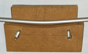
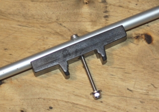
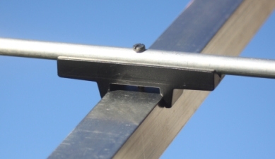
1. WiMo, Konni, EA4TX, Nuxcom element holders - Numbers published by DG7YBN
The photo shows the method of semi insulated mounting of 8 mm elements. Note the reinforcing plate (WiMo - YU7EF series) and self locking nut. The reinforcing plate does not change much in frequency (less than 50 KHz up). The BC numbers table is valid with and without these. They are hardly to be noticed on the Analyser at all - but they do improve mechanical stability a lot.
Applies to a building style using SQUARE booms, screws and insulators
made from glassfibre reinforced black plastic, see specs in table below
Base BC: If you are in doubts if the BC works correctly, here is an example: click
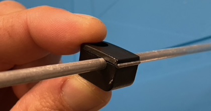
2. Numbers published by DG7YBN
Applies to a building style using ROUND booms, screws and insulators
made from glassfibre reinforced black plastic, see specs in table below Screws M3 - 1.4301 stainless (Ansi SS316)
Those insulators are also sold by Konni Antennen, Nuxcom, EA4TX.
They are available in Imperial units too, please interpolate data.
Round boom insulators will need a correction factor BC * 0.x
These numbers are derived by building Test-Yagis in quanities and measuring them with miniVNA and HP Analyser.
Achievements & Feedback: EME DXpeditionär Peter, DL1RPL on his choice using the YU7EF EF7017 in building style as prototype for series WiMo, with this On-Boom-BC for FH/DL1RPL & FR/DL1RPL 2015. Take a look at the antennas
“The EF7017 70cm-antennas expectedly worked very good. I had build and tested several antennas at home (sun noise, RL), but the EF7017 was clearly the best (Thanks to Hartmut, DG7YBN for his excellently optimised prototype built!). 36 QSO's in one (moon) path on 70cm was great.“
(Note: this is not necessarily an appeal to use these insulatores BUT to use proper BC numbers and right segmentation density in models OR compensate segmentation density with the SBC factors given down the website)
Download the BC Calculation Excel with a mode for Semi-Insulated Ele. On-Boom from here
3. SM7DTT element holders (former VHF Teknik) - Numbers published by DG7YBN
Insulator specs:
4. LA4ZH Holders (www.Eidolon.no) - Numbers published by DG7YBN
LA4ZH's large holders as a case study
They are very high and also do touch the element on very little surface.
I strapped the Ø 5 mm element on with 2 pieces of 2.4 mm cable straps.
Material is PA6 GF30 'natural' with 30 percent glassfiber filling
Insulator specs:
5. 7arrays Holders - Numbers published by DG7YBN
Insulator specs:
6. Stauff Light Series Clamps / measured by IZ2IVF
Stauff Light Series Type: LB-103.2-PP
IZ2IVF writes: "Internal diameter is 3.2 mm, so my 4mm elements fits perfectly inside with a bit of pressure"
Insulator width = 12 mm, element freeboard above boom = 7 mm
7. Folded Sheet Metal (CueDee, WiMo xpol) - Numbers published by VE7BQH

Applies to conductive element mounts made from bent sheet metal.
Check on those mounts length, as it is a very important parameter here! Numbers below are for 144 MHz only.
Online DL6WU / G3SEK Boom Correction Calculator
Note the twin output (1) for building with insulation parts through boom and (2) for conductive mounting through boom
Read more on the DL6WU Boom Correction below.
Conductive thru boom elements building style
The DL6WU / G3SEK formula appears in two versions and derivates. Nevertheless - over the useful span their results are absolutly identical.
"Press fit" in sketch means a durable good electrical contact. Unless you are capable of applying a tiny welding seam from element to boom we find that building style only on Microwaves (see below) where the short elements are punched into the boom with a hammer. There are commercial builds which use a semi thru boom conductive mount like Tonna or Flexa Yagi. Here the elements are clamped or screwed onto the booms face. As the labile electrical contact achieved is somewhat questionable those builds need a quite wideband forgiving design - or performance will degrade by time.
1. From G3SEK's Long Yagi Workshop:
2. The DL6WU / G3SEK formula in classical notation
3. From VK2KU's - Effects of Boom and Element Diameters on Yagi Element Lengths at 144, 432 and 1296 MHz - QEX Jan/Feb 2000:
This is how I have set this formula to enter and return dimensions in millimetres:
Note 1: This formula is not valid at boom diameters greater than 0.055 lambda
Note 2: These formulas do not reflect on element diameter nor element length.
Insulated thru boom elements building style
1. The DL6WU / G3SEK formula in classical notation
The formula set to derive just the Boom Correction
This is how I have set this formula to enter and return dimensions in millimetres:
Note 1: This formula is not valid at boom diameters greater than 0.055 lambda
Note 2: These formulas do not reflect on element diameter nor element length
Take number from following chart or (3.) VE7BQH below
2. Numbers published by DJ9BV
Applies to a building style thru SQUARE boom
3. Numbers published by VE7BQH
Applies to a building style thru round AND square boom
144 MHz numbers are derived from DL6WU/G3SEK formula
432 MHz midfield numbers degrade by a few tenth from DL6WU/G3SEK
4. Numbers published by K1FO
Applies to a building style thru round boom
5. Numbers published by I0JXX
Applies to a building style thru round boom
6. Summary
Looking through the tables above we note some difference between the numbers. This might be due to using different details in the actual styles of building. Hole-in-Boom sizes, insulator geometries and materials ... all the details we do no find in the sole BC numbers might account for this. Consequently, if you chose to follow one out of the 5 sets presented, you will do good in following the particular style of building too.
Read further - SM5BSZ's BC.exe encloses most of the vacant parameters and thus might be able to derive best of all numbers on insulated thru boom correction.
BC.exe by SM5BSZ for insulated thru boom building style
BC.exe by Leif Åsbrink is based on a set of precise measurements taken on fractions of boom rod and elements in a resonace chamber. The effective parameters are
BC.exe processes a text file named 'INPUT.BC' to another text file named 'OUTPUT.BC' when the BC.exe is called up. All within some milliseconds. BC.exe pops up in a DOS console, handles the few lines enclosed in the input file, writes the output file and shuts down again. Actually you might just see a glimps of the BC.exe's console at work and away it is. Attention: BC.exe delivers numbers for 144 MHz only (see below). However a modified BC.exe that scales frequency is for download below (s. SM5BSZ BC.exe modified for use at other Frequencies).
The 'INPUT.BC' file must be edited very carefully. The columns scheme needs to be followed exactly as in the example given. The Fortan coded .exe picks the numbers from no other then these expected places. Use the decimal points as anchors around which the numbers may be modified. Find a scheme how to enter your input data at SM5BSZ's website, see link below.
Below you find an example INPUT.BC file holding a real 7 element Yagi.
Note the last column - holding distance to nearest boom end instead of position on boom.
Call up the BC.exe file, which will vanish again immediately ... it took several attempts to do the screenshot
(it is on a different file)
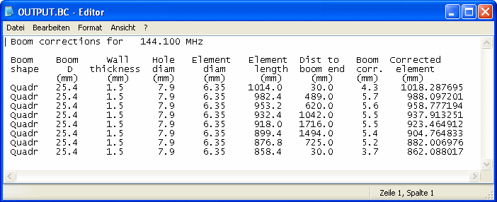
And this is what the OUTPUT.BC file looks like
Edit / look up the 'INPUT.BC' respectively 'OUTPUT.BC' with any basic text editor. I use 'Notepad++', anyway win 'editor' will do the job.
The original BC.exe will only compute correctly for 144 MHz.
Link to SM5BSZ website on BC.exe
Open the above INPUT.BC in a new browser tab, copy content to a .txt file
save to same folder as your BC.exe, name it INPUT.BC and run it.
The SM5BSZ BC.exe modified for use at other Frequencies
BC.exe modified for effective frequency input but unverified on real builds other than 144 and 432 MHz. This is the modifed and compiled Fortran code that uses corrected scaling formula as originally intended. These modifications have been carried out by VE7BQH under consultance of SM5BSZ.
A 432 MHz INPUT.BC file showing a real Long Yagi
And this is what the OUTPUT.BC file looks like
Download BC.exe modified 32 bit Vers. 3 as a .zip file; including some sample INPUT.BC files and a readme.txt.
Download BC.exe modified 64 bit Vers. 1.0 as a .zip file; including sample INPUT.BC file
The 64 bit version runs on win7 and 8 and writes to a file named "OUTERR.txt" that shows whats wrong when BC.exe does not compute.
The OUTERR - file is an extension by me, same as the portation to Fortan 95 in order to compile the BC.exe to a 64 bit .exe file.
Download Source Code of the modified BC.exe including writing to OUTERR - file
Please note:
1. This modified BC.exe this far is not tested on real Yagi for all frequency range other than 144 and 432 MHz
2. Plastic insulators large in size at applied wavelength are not compensated in BC.exe
3. No guarantee is given on this modified BC.exe, whatsoever, use BC.exe at your own risk.
4. BC.exe and its source code are the sole property of Leif Asbrink, SM5BSZ.
The sample INPUT.BC files hold a number of Yagis and test configurations. Each divided by a space line. BC.exe stops computing when reaching an empty line. Copy - Paste or modify what you like and place the lines you like to have computed directly below the frequency in first line. Add space between the other lines you may like to keep and run BC.exe.
UA3TZ's boom.exe - another Correction that adds Boom Ends Influence
Boom-e.exe is a DOS console program by Anatolij I. Grechikhin, UA3TZ
In contrast to most known corrections it also takes into account the distance to a boom end for elements mounted on the boom. Its output is a non uniform BC per element like we see with BC.exe by SM5BSZ, which is determind for correcting elements mounted insulated through boom.
Example : 144 MHz 2.5 wl Yagi, non uniform Boom Correction according UA3TZ
This is 4 mm elements mounted insulated through a 20 mm boom, first & last element at 20 mm from boom end. Note the dependency of BC number per element to its mounting position from boom end (this looks almost same in shape, with different numbers though in SM5BSZ BC.exe, see next chapter)
Link to external website with UA3TZ's article about this Boom Correction.
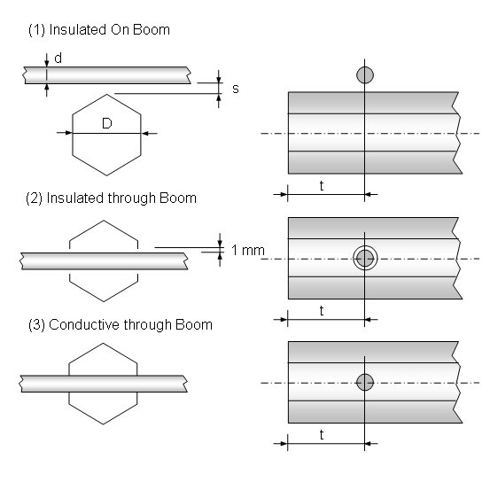
It handles 3 types of element mounts:
Working with boom-e.exe
• Choose type of element mounting style 1, 2 or 3 style & enter
• Fill in element diameter & enter
• Fill in boom diameter & enter
• Fill in distance to nearer boom end & enter
• Fill in space between booms upper face and element (#1 on boom elements only) & enter
For next element type "1" for option '1 - other data' and proceed
Download Link to external download website www.radioscanner.ru
The program is enclosd in two languages
boom-e.exe = Version in English Language
boom-r.exe = Version in Russian Language
Tnx to Vladimir, UR5EAZ, who introduced this program to me
Comparing SM5BSZ BC.exe and UA3TZ boom(-e).exe
Example: Elements mounted insulated through boom
432 MHz - Influence of approaching the ends of the boom tube computed with BC.exe by SM5BSZ and boom(-e).exe by UA3TZ. Filled into the chart is the correction of 340 mm long elements in millimetres for a 20 x 20 x 2 mm square and Ø 20 mm round boom. Elements are of 4 mm in diameter. Elements lengths are frozen at 340 mm each to show a comparable set of numbers at varying distances to the nearer boom end.
The insulator holes in the boom of Ø 6 mm may ressemble nylon rivets (DL6WU/DJ9BV) or plastic bore hole end plugs (7YBN).
Comparing DG7YBN On-Round-Boom and UA3TZ boom(-e).exe
For this test I used a 30 mm round boom, 8.0 mm elements, 1.8 mm clearence between element and booms face
and a variety of distances for the 'distance to boom end' sensitive boom.exe
to the lenght the element is covered) and M3 screw through element and boom.
Non Uniform BC on all Elements & Boom Ends Influence
In the experts chats on moon net and elsewhere we note a great interest in if a BC needs to be adaptive to the element length. In my opinion we have to separate two causes her, since there are two mechanisms at work that degrade BC numbers on far out elements.
1. Insulated thru boom BC only
The BC.exe by SM5BSZ for insulated thru boom element mounting shows us that here there is a dependance of BC as function of distance to the nearest boom end. Just to give some orientation numbers: On a round 25 mm boom at 144 MHz the maximum decrease of BC is approximately 25% . Degradation starts very gently at a distance to the end of approximately 1 λ . Then falling rapidly when approaching the end.
The mechanism at work is that the little piece of element enclosed in the boom tube radiates to a fraction of what radiates outside. The booms inner space acts as a cavity, with different influence towards the boom ends. This is the reason, why BC.exe has the inner boom diametre enclosed in its parameter set as 'wall thickness'.
Example 1: 432 MHz 19 Elem. Yagi (GTV 70-19m) - Influence of approaching the ends of the boom tube computed with BC.exe by SM5BSZ. Filled into the chart is the correction of the elements in millimetres for a 20 x 20 x 2 mm square boom. Dipole and elements are of 4 mm in diameter. The insulators are nylon rivets (DL6WU/DJ9BV) or plastic bore hole end plugs (7YBN) with 6 mm holes in the boom. On display is the superposition of the parameters (a) "Influence of nearer end of boom" and (b) "Length of the element".
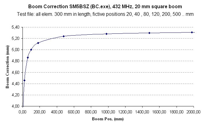
Example 2: 432 MHz - Influence of approaching the ends of the boom tube computed with BC.exe by SM5BSZ. A fictitious sample to show the dependency of correction number applied to the element length to the distance to the nearer end of a boom. Because the element length is a parameter in BC.exe as well, the elements lengths are frozen at 300 mm each to show a comparable set of numbers at varying distances to the nearer boom end.
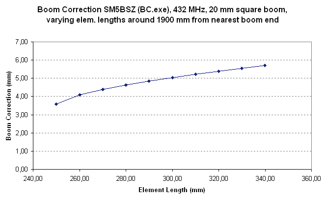
Example 3: 432 MHz Yagi Elemente - Influence of element length on correction number with sufficent distance to booms ends. Also computed with BC.exe by SM5BSZ. Filled into the chart is the correction of the elements in millimetres for a 20 x 20 x 2 mm square boom. The insulators are nylon rivets (DL6WU/DJ9BV) or plastic bore hole end plugs (7YBN) with 6 mm holes in the boom. On display is the alternation of the correction number over a variation of element lengths as parameter at a virtually fixed position on (.. through ..) the boom tube
 Tip! Those who wish to study the influence of approaching the boom ends
further can do this in a convenient way with the MS Excel Yagi Element Configuration Tool. Just fill in constant element lengths into a model in
SM5BSZ BC.exe mode and set element positions very close towards the boom ends. Then compute and choose the columns "Base-BC" and "Boom Position"
as x and y range in a chart. The charts shown were produced in similar way.
Link to this tool click
Tip! Those who wish to study the influence of approaching the boom ends
further can do this in a convenient way with the MS Excel Yagi Element Configuration Tool. Just fill in constant element lengths into a model in
SM5BSZ BC.exe mode and set element positions very close towards the boom ends. Then compute and choose the columns "Base-BC" and "Boom Position"
as x and y range in a chart. The charts shown were produced in similar way.
Link to this tool click
2. All types of mounts
Same as mentioned according the form of the decrease will appy to the outside of the ending tube. Just on far less distance. An element nestling als very first or last close to a boom end will see much less Boom when the boom is cut sharply behing the element position. So that it sees almost only half of the amount of boom volume present Since aware of that we have cut all Test-Yagi booms for the On Boom BC with 30 to 40 mm excess length on first and last elements position. The published analyser plots show that this was a good idea and the right thing to do. If the exact correction is known one can resign from adding that excess lengths to the boom but shorten the BC on the far elements. The SM5BSZ BC.exe seems to encloses this mechnism too.
Microwaves conductive through boom
from corrosion by painting with clear coat.
Further Details
1. In DJ9BV's - "DL6WU Yagis for 23 cm" - Dubus 2/1994 we find Ø 4 mm elements made from aluminium AlMgSi1
to be pressed into a Ø 3.9 mm hole in a Ø 15 mm boom.
2. In DJ9YW's - "A Homebrew Yagi for 1296 MHz DX" - Dubus 1/2006 we find Ø 3.2 mm elements made from
aluminium AlMg5 to be pressed into Ø 3.1 mm holes in a square 15 x 15 x 1 mm boom.
3. In DC3XY's - "DL6WU-Yagi for 2320 MHz" - Dubus 4/1989 we find Ø 2.4 mm AlMg3 elements pressed into
Ø 2.3 mm holes in a square AlMgSi 10 x 10 x 1 mm boom.
Don't try this at home ... unless you absolutely stick to the data and geometries given in the above articles. Despite a more or less proven BC is given here, I advise not to be overoptimistic. For good reasons the mentioned designs are of very forgiving DL6WU style. Do not try this on a high Q-factor designs unless you are very skilled in building and measuring Yagis plus have at least a network analyser that covers the foreseen GHz band at hand.
Alternatively elements can be placed in a secure height above boom using offset insulators, as seen on the 1296 and 2320 MHz Tonnas and I0JXX.
Note that the NEC2 manual holds a passage where it states that at very high frequencies well above 432 MHz a tube end may have the effect of a small capacity against that of a solid rod. Thus a tube elements electrical lengths will be inflicted by this. Numbers given are a vague as this. But I thought this to be worthwhile to be forwarded in this context.
What may obscure right BC measures
The Yagi may be divided into three zones
1. Getting the coax cutting done right
 Attenzione!
It is understood that a length of coax cable needs to be shortened using its velocity factor if we want to cut a resonate
length. A waves speed in a medium is described as
According IEC 60250 the dielectrical constant εr of (natural) PTFE is 2.1, measured at 1 MHz equalling v = 0.690 = 69%. However Radio Amateurs mostly use v = 0.7... 0.71 so that the calculated length of a 144 MHz Quarter Wave Line is around 369 mm.
But have you ever measured the resonance frequency what you have cut? At VHF and above you will probably be surprised to find your stub being some 5...10% too low in resonance frequency. This is due to εr and v-factor being specified at a much lower frequency and plastics dielectrical properties are frequency depending to a certian extend.
From left to right: DK7ZB match, λ/2 Balun, Quarterwave line
The full story is that plastics hold a so called Dynamic Dielectrical Constant.
 Find more information on Phasing & Matching Lines page
2. Why is an exact length of the coax balun or quarter wave line that important?
Any excess length of our matching network will virtual add to the Driven Elements span width. Example: A quarter wave line for 144.1 MHz made from PTFE coax RG-142 B/U has a length of 369 mm when calculated using the commonly used v-factor of 0.7. The lines length when carefully tuned to resonace as a quarterwave line at 144.1 MHz with aid of a Network Analyser is 345 mm. The 24 mm or 7% of excess length will affect the VSWR we measure on the complete arrangement of the Yagi plus matching network.
Read more about the outcome of such imperfections in my article 'Applied Conversion of Segmented Wires from NEC to 144/432 MHz Yagi Elements - Part 3' in Dubus 2/11.
Boom Correction and NEC Models Segmentation
What happens if we vary the segmentation density of the Elements (Wires) in a NEC model?
We see the impendance resonance peak shift in frequency. The three plots below show the same 2m Yagi. Just with increasing segmentation density from one Return Loss plot to the next plot. The Numbers given show stepped segmentation densities, wherein the reflector uses most segments (starting number) and running along the elements getting less as length drops until we reach the last direction parasitic element. That way each segment is of almost same length, which results in best model accuracy we can get from NEC.
5 elem. DUT Yagi => 11 ... 9 segments (EZNEC Auto Segmentated at 144 MHz)
5 elem. DUT Yagi => 16 ... 13 segments (EZNEC Auto Segmentated at 220 MHz)
5 elem. DUT Yagi => 24 ... 20 segments (EZNEC Auto Segmentated at 340 MHz)
5 elem. DUT Yagi => 43 ... 36 segments (EZNEC Auto Segmentated at 620 MHz)
What RL plot will representate the true plot shape for a boomless build as base for adding a BC?
Deriving the SBC component
It is of vital importance to find the fitting segmentation density that corresponds with your kind of antenna - or better said - the way the applied NEC kernel deals with the challenges enclosed in the very model. To enclose the influence of models segmentation in the BC theory I have introduced the 'Segmentation BC' (SBC) component. Actually it is not a BC challenge by classical means. Traditional BC numbers are meant to be applied on a Yagi that is exactly on frequency as a boomless real world build.
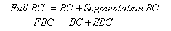
The SBC will help in converting wires from NEC to real world builds. This additional SBC bridges over from not fitting segmentation densities to a corresponding with boomless builds densities by determinating the gap in both models resonace peak frequencies. The difference in frequency is equal to an extra portion of BC in millimetres.
In doing so the SBC does what is often not realised when applying likewise DL6WU/G3SEK BC numbers on whatever model and expecting the ingenuity of DL6WU to solve all challenges.
Run your model twice. Once with segmentation density as designed with, note resonace peak frequency. Do a second run with boomless builds density, note that frequency too. Calculate the delta in frequency. Multiply by factor given in table below to gain the SBC in millimetres which must be added to the common BC.
How does it occure and what sign must the SBC's correction length have?
Here we have to think out of the box [Dt: "um die Ecke denken"]. A designer is convinced that a segmentation density somewhat higher than what would represent the actual boomless build is a good choice. So he designs his Yagi with the consequence that by using the higher segmentation density an element of same length will virtually appear longer to the NEC Kernel that at true density applied. Consequently he will shorten all elements in his NEC model by that amount in order to end up with a model simulation resulting in the seeked frequency as resonace peak. Simulating this design using the corresponding to boomless build segmentation will derive a higher in frequency resonance peak. The real world build would be too high by that amount. This we neutralise by adding the right SBC in millimetres. In the opposite case of a Yagi designed with less segments that corresponding to boomless build the amount will have to be subtracted.
The SBC ...... a Segmentation Density (Boom) Correction
The SBC covers different segmentation numbers used on individual designs or by individual designers for best conversion of the NEC geometry into numbers for a real world build in addition to applying the common BC to adapt to an individual style of building and boom dimensions.
How to apply?
What numbers to use?
Both, boomless builds segmentation density and factor to transform the SBC to millimetres must be derived by measurements on real builds. For a conventional Yagi by means of a straight split DE and no quad style or sharply bent parasitc elements the corresponding to a boomless builds segmentation density is very close to what you get using EZNEC's auto segmentation function at the antennas designated frequency. That is around starting with 11 at the reflector and going down to 9 segments for the far out directing elements. For a Yagi with loop fed Driver Cell like the G0KSC LFA this is around 30+ segments, this equals what you get when using EZNEC's auto segmentation function at around 420+ MHz.
Multiplication factors for deriving the SBC in millimetres
An Example:
A highly segmented 144 MHz Yagi Design shows best simulated RL on 144.3 MHz,
Auto Segmented at 144.1 MHz => simulated best RL shifts up to 144.7 MHz
SBC = delta freq. * Factor = 0.4 MHz * 5.85 mm/MHz = 2.3 mm
Overview: Yagi element length correction numbers per MHz/mm in a chart
 basically tested
 fully tested
Overview: Yagi element length correction numbers per MHz/mm in a chart - 0 ... 500 MHz
Overview: Yagi element length correction numbers per invers value mm/MHz in a chart
If we do not enclose the SBC but trim a Yagi designed using a high segmentation density to wanted frequency
by manipulating DE and D1 ... at the end of the day we might get the Yagi to have its VSWR low where we want it to
be finally. But the directing parasitic elements and reflector will fall short by the amount of SBC. So that by this, plus the
manipulation done to the Driver Cell neither radiation pattern nor whatever data from gain to F/B or antenna temperature will be
exactly as designed.
Some Permittivity Numbers
DG7YBN Yagi Element Configuration Tool
This MS Excel Tool is the follow up of my On-Boom-BC Excel. Current Version No. is 1.51
DG7YBN Yagi Element Configuration Tool, Vers 1.51
Key features
• Computes BC according DL6WU, SM5BSZ and DG7YBN for Elements insulated on Boom
• Amateur Bands 50 to 432 MHz
• NEC file import from 4nec2
• Data base that can be imported / exported to CSV format
• Basic beta-version of a Yagi windload calculator
• It is tested with MS Excel 2003 on winXP, MS Excel 2007 on winXP, MS Excel 2010 on win7
Sorry win98, win2000 and MS Excel from the 97 MS Office are not supported.
Neither will any 64 Bit Excel run all features - several runtime to debug scenarios are known.
A 64 bit OS itself is no problem but the 64 bit Excel is.
However, your MS Excels Safety Settings must be set to enable Macros since this Calculator
holds in excess of 8000 lines of Visual Basic Code.
Disclaimer: this Excel contains macros.
Use only downloads from a safe source; Use is at own risk whatsoever (!)
To download the zipped tool go here
Note: The logos, notations, brands and trade names shown or mentioned on this website are the property of the
correlating companies and are subject to trademark rights !
73, Hartmut, DG7YBN
Through the transformation into a real low noise pick up, side lobes supressing, yet high gain antenna the development of the Yagi-Uda has made a large progress since about 2005. All due to faster personal computers, better NEC frontends and nec4 kernel initail designs by YU7EF and the follow up designer lot. And a new 'dimension' of measurement accuracy due to affordable antenna analysers. Additionally the reintroduction of low impedance Yagi-Uda structures (not necessarily a low impedant feedpoint, see LFA loop and bent Dipoles) adds more than gain today. But in order to take full benefits of this forward development the call for precise element lengths and positions is more urging then it ever was. Hence Boom Correction (BC) is a serious topic!
Do not build following plans that just state to add 2 mm or give vague information only. You can do better then that. Read carefully and note that all the mentioned BC - factors reflect on a specified way of mounting the elements. Whatever you chose to build and how, the BC must match the forseen way of mounting the elements. If likewise using 'DJ9BV numbers' you have to stick to the mentioned nylon rivets, square boom and 4 mm elements.
To complete the package the way of matching or balancing the feed and the realisation of feedpoint and dipole housing must fit the picture too. Find plenty of additional information on my "Building a Yagi" and "Symmetrising and Baluns" website.
Wishing you happy building of better Yagis! 73, DG7YBN
Acryl insulator on photo above is a self machined demonstration piece
Basics: Boom Correction numbers (BC) are given as lengths to be added to the "free" length of the element. As in NEC we simulated without any boom - The BC compensates for the influence of boom and mounting bracket. All the BC numbers below are "add-to-full length". To make this clear: the example shows an ele. of 940.0 mm from NEC geometry, BC is 3.9 mm, total cutting length is 943.9 mm.

Any BC numbers are depending on the actual building style. Basically element mounting styles may be rationed in
1. Conductive through boom
2. Insulated through boom
3. On boom (fully or semi-insulated)
In fact we may use more details than enclosed in the Old School approach, such as
2'. Insulated through boom    -  at what distance to boom tube ends?
2'. Insulated through boom    -  using what hole diameter?
2'. Insulated through boom    -  using what insulator material and geometry?
3'. On boom (fully insulated) -  at what distance, using what insulator material and geometry?
3'. On boom (semi insulated)  -  as above + using what screw or bolt?
+ . First and last Element    -  fading influence of outer booms presence when cut sharply?
In the past we have seen a set of BC numbers that are established now by means of being granted, such as DL6WU and later extended G3SEK / DL6WU. Today we use them unbalanced for whatever Yagi-Design and its models segmentation. Is that feasible when we want a real world Yagi with optimum performance? In case you might wonder why there are no specifications included for using round or square boom? =>
From SM5BSZ website: Traditionally there is [... was...] no difference in correction factor [.. published...] for round or square booms.
In the source code of SM5BSZ's BC.exe we find a line refering to influence of square and round boom shapes. He computes an equivalent boom diameter D by multiplying with a factor of 1.18 for any square boom. So that the equivalent diameter for computing the elements BC is 18% larger for any square boom as for any round boom of same diameter. As all factors given in the BC.exe are based on very carefully executed measurements this relation of 18% might be considered for any other insulated through boom BC as DL6WU/G3SEK, DJ9BV, K1FO etc. as well. Always mind the base (round or square boom) the specific BC was set up with. That is why I have added the settings the BC was produced with to the following list of BCs. Like "applies to square boom, nylon rivets, 4 mm elements and 6 mm hole in boom" in case of DJ9BVs BC.
Another thing that applies to the following original DL6WU/G3SEK formula set is the habit to focus on Correction numbers as fractions of boom diameter in wavelengths. Perhaps as a reverberation of the first methodical papers on Yagi design by P.P. Viezbiecke and others. In straight words - these original formulas do not deliver an element length correction in millimeters right away. Set up by antenna analytics they deliver analytical data on Yagi element behaviour in general. Using the wavelength as reference is a perfect way to express a Boom Correction in a generalised way.
A real pain though, if you want nothing but the needed extension on an actual Yagi you want to build. The terminology and formula symbols B for boom diameter, C for Correction and C/B as their fraction as numbers in wavelength might look misleading if you do not consider this background and are just seeking for a BC in millimetres.
When comparing the two DL6WU/G3SEK formulas one easily recognises that the resulting BC numbers for conductive thru boom are exactly twice the number for insulated thru boom. So that if you do not wish to calculate much you might just pick your BC from one of the table rows given for insulated thru boom, multiply by 2.0 and derive a BC for conductive thru boom.
It is understood that all BC numbers apply to a half wave element - which is a full element on any standard Yagi.
BC numbers are for boomless 'on spot' only
It seems to have established that whatever design at whatever segmentation density would be cured by simply applying DL6WU or other approved Boom Correction.
Read carefully: All of the Old School BC formulas use Yagis that are already 'on spot' when build on cardboard, wooden or plastic boom as their base line. A build that is as close to free air as managable. Then this set of elements was placed on a metal boom and element lengths adapted until the frequency response measured on wooden boom was restored. That is how these numbers were derived and how they should be applied.
Today we tend to wish to go from NEC model to real world build directly - but it is easy to note the shift in frequency by several 100 kHz when modelling and computing a NEC based design at a variety of segmentations. How could formulas that do not hold the segmentation compensate for that? ... they do not, they can't deliver on that and were never ment do so.
Consequently we have to carefully chose a fitting segmentation or seek an additional compensationg factor - the Segmentation Density BC (SBC).
On boom elements using standard insulators building style
1. WiMo, Konni, EA4TX, Nuxcom element holders - Numbers published by DG7YBN


The photo shows the method of semi insulated mounting of 8 mm elements. Note the reinforcing plate (WiMo - YU7EF series) and self locking nut. The reinforcing plate does not change much in frequency (less than 50 KHz up). The BC numbers table is valid with and without these. They are hardly to be noticed on the Analyser at all - but they do improve mechanical stability a lot.
Applies to a building style using SQUARE booms, screws and insulators
made from glassfibre reinforced black plastic, see specs in table below
Base BC: If you are in doubts if the BC works correctly, here is an example: click
Boom Dim.       144 MHz       432 MHz         403 MHz (Radio Sonde Band)
15 x 15 mm      2.7 mm        4.8 mm           -
20 x 20 mm      3.9 mm        7.5 mm          7.1 mm **
25 x 25 mm      7.6 mm       11.5 mm         10.4 mm **
30 x 30 mm    (10.4 mm)*    (14.4 mm)*         -

*) by interpolation in comparison with G3SEK/DL6WU chart lines
**) interpolated between 144 an 432 MHz

144 MHz elem. Ø = 8 x 1 mm tube
432 MHz elem. Ø = 6 mm solid rod, thread in rod, screw upside down and ends sharply at element face

Screws M3 - 1.4301 stainless (Ansi SS316)

Insulator specs: PA6 with encapsuled carbon black filler (PA6.6 GF30)

Boom [mm]             15 x 15     20 x 20     25 x 25     30 x 30     35 x 35
Length along elem.     57 mm       59 mm       70 mm       70 mm       70 mm
clearance*            3.7 mm      3.1 mm      1.7 mm      1.7 mm      1.7 mm

*) lower face of element to upper face of boom

Type         15 x 15      20 x 20      25 x 25      30 x 30
WiMo        #23040.15    #23040.20    #23040.25    #23040.30
2. Numbers published by DG7YBN

Applies to a building style using ROUND booms, screws and insulators
made from glassfibre reinforced black plastic, see specs in table below Screws M3 - 1.4301 stainless (Ansi SS316)
Boom Dim.       144 MHz       432 MHz
20 x 20 mm      x.x mm        x.x mm
25 x 25 mm      x.x mm       xx.x mm
30 x 30 mm      4.4 mm       xx.x mm
35 x 35 mm      x.x mm       xx.x mm

Insulator specs: PA6 with encapsuled carbon black filler

Boom                  Ø 20 mm     Ø 25 mm     Ø 30 mm     Ø 35 mm
Length along elem.     xx mm       xx mm       70 mm       xx mm
clearance*            x.x mm      x.x mm      1.8 mm      x.x mm

*) lower face of element to upper face of boom
Those insulators are also sold by Konni Antennen, Nuxcom, EA4TX.
They are available in Imperial units too, please interpolate data.
Round boom insulators will need a correction factor BC * 0.x
These numbers are derived by building Test-Yagis in quanities and measuring them with miniVNA and HP Analyser.
Achievements & Feedback: EME DXpeditionär Peter, DL1RPL on his choice using the YU7EF EF7017 in building style as prototype for series WiMo, with this On-Boom-BC for FH/DL1RPL & FR/DL1RPL 2015. Take a look at the antennas
“The EF7017 70cm-antennas expectedly worked very good. I had build and tested several antennas at home (sun noise, RL), but the EF7017 was clearly the best (Thanks to Hartmut, DG7YBN for his excellently optimised prototype built!). 36 QSO's in one (moon) path on 70cm was great.“
(Note: this is not necessarily an appeal to use these insulatores BUT to use proper BC numbers and right segmentation density in models OR compensate segmentation density with the SBC factors given down the website)
Download the BC Calculation Excel with a mode for Semi-Insulated Ele. On-Boom from here
3. SM7DTT element holders (former VHF Teknik) - Numbers published by DG7YBN

Insulator specs:
Boom [mm]             12 x 12     20 x 20     25 x 25**   30 x 30**   35 x 35
Length along elem.    17.2 mm     25.5 mm     25.5 mm     25.5 mm       --
clearance              8.3 mm      7.5 mm     15.3 mm     16.9 mm       --

(**) with adapter plate underneath the 20 x 20 mm version
Boom Dim.       144 MHz       432 MHz         403 MHz (Radio Sonde Band)
12 x 12 mm       --             --              --
20 x 20 mm      2.3 mm         4.2 mm            --
25 x 25 mm       --             --              --
30 x 30 mm       --             --              --
4. LA4ZH Holders (www.Eidolon.no) - Numbers published by DG7YBN
LA4ZH's large holders as a case study
They are very high and also do touch the element on very little surface.
I strapped the Ø 5 mm element on with 2 pieces of 2.4 mm cable straps.
Material is PA6 GF30 'natural' with 30 percent glassfiber filling

Insulator specs:
Boom [mm]             16 x 16     20 x 20     25 x 25     30 x 30     35 x 35
Length along elem.(a) 36.0 mm     36.0 mm     36.0 mm     36.0 mm     36.0 mm
clearance             15.0 mm     15.0 mm     19.0 mm     19.0 mm     19.0 mm

(a) = for all, of which touching the elem. = 8 mm only
Boom Dim.       144 MHz       432 MHz
12 x 12 mm       --             --
20 x 20 mm       --           3.4 mm
25 x 25 mm       --             --
30 x 30 mm       --             --
5. 7arrays Holders - Numbers published by DG7YBN
Insulator specs:
Boom [mm]             25 x 25
Length along elem.    70.0 mm
clearance              6.5 mm
Boom Dim.       144 MHz       432 MHz
25 x 25 mm      3.7 mm        7.1 mm
6. Stauff Light Series Clamps / measured by IZ2IVF
Stauff Light Series Type: LB-103.2-PP
IZ2IVF writes: "Internal diameter is 3.2 mm, so my 4mm elements fits perfectly inside with a bit of pressure"
Insulator width = 12 mm, element freeboard above boom = 7 mm
Boom Dim.       144 MHz       432 MHz
12 x 12 mm       --             --
20 x 20 mm       --           5.6 mm
25 x 25 mm       --             --
30 x 30 mm       --             --
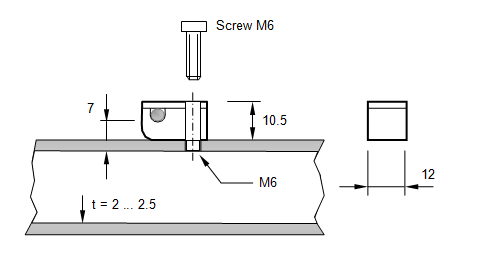
7. Folded Sheet Metal (CueDee, WiMo xpol) - Numbers published by VE7BQH
Applies to conductive element mounts made from bent sheet metal.
Check on those mounts length, as it is a very important parameter here! Numbers below are for 144 MHz only.
     From the VE7BQH G/T 144 MHz table, Issue 75 - April 25, 2010

    "CORRECTION FACTOR FOR CUSHCRAFT AND CUDEE STYLE MOUNTED ELEMENTS

    CUSHCRAFT CORRECTION FACTOR ON 2 METERS = .3125" OR 7.94MM
    CUDEE CORRECTION FACTOR ON 2 METERS     = .2500" OR 6.35MM"
Online DL6WU / G3SEK Boom Correction Calculator
Note the twin output (1) for building with insulation parts through boom and (2) for conductive mounting through boom
Imperial to metric boom dimensions

	1/2 in    =  12.700 mm
	5/8 in    =  15.875 mm
	3/4 in    =  19.050 mm
	7/8 in    =  22.225 mm
	1 in      =  25.400 mm
	1 1/4 in  =  31.750 mm
	1 1/2 in  =  38.100 mm
	1 3/4 in  =  44.450 mm
	2 in      =  50.800 mm
	2 1/2 in  =  63.500 mm
	3 in      =  76.200 mm
|
|
Attenzione! Be sure to add the appropriate Segmentation-BC (SBC) for any NEC model that uses high segmentation density, except for LFAs, Quads and Quagis. Read about Boom Correction and NEC Models Segmentation further down or click here. |
Read more on the DL6WU Boom Correction below.
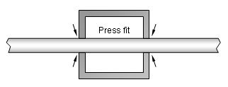
Conductive thru boom elements building style

The DL6WU / G3SEK formula appears in two versions and derivates. Nevertheless - over the useful span their results are absolutly identical.
"Press fit" in sketch means a durable good electrical contact. Unless you are capable of applying a tiny welding seam from element to boom we find that building style only on Microwaves (see below) where the short elements are punched into the boom with a hammer. There are commercial builds which use a semi thru boom conductive mount like Tonna or Flexa Yagi. Here the elements are clamped or screwed onto the booms face. As the labile electrical contact achieved is somewhat questionable those builds need a quite wideband forgiving design - or performance will degrade by time.
1. From G3SEK's Long Yagi Workshop:
    "A useful formula for boom corrections is:

    BC = [733 * BD * (.055 - BD)] - [504 * BD * (.03 - BD)]

    where BC is the correction as a fraction of boom diameter BD (both in units of wavelengths).
    Boom-effect correction must always be added to the uncorrected element length. [...]
    This formula is derived from experimental work by DL6WU, and applies to elements passing
    through a round boom."
2. The DL6WU / G3SEK formula in classical notation
    C = 25.195 * B - 229 * B^2

    C = Boom Correction as fraction of boom diameter B, both in [wl] => [ / ]
    B = boom diameter   [wl]
    ^2  means squared
3. From VK2KU's - Effects of Boom and Element Diameters on Yagi Element Lengths at 144, 432 and 1296 MHz - QEX Jan/Feb 2000:
    C/B = 25.195 * (B/λ) - 229 * (B/λ)^2

    "... where C is the correction and B is the boom diameter, both in millimeters."
    [C/B = ratio - correction length to boom diameter in wavelength]
This is how I have set this formula to enter and return dimensions in millimetres:
BC = [25,195 - 229 * BD/(λ*1000)] * [BD/(λ*1000)]^2 * λ*1000

BC = Boom Correction [mm]
BD = boom diameter   [mm]
λ = wavelength       [m]

c = 299.792.458 m/s
λ = c/f[Hz]  =>  in SI units  =  [ms]/[1/s] = [m]
For convenience use frequency in MHz * 10^6 = Hz = 1/s
Note 1: This formula is not valid at boom diameters greater than 0.055 lambda
Note 2: These formulas do not reflect on element diameter nor element length.


Insulated thru boom elements building style


1. The DL6WU / G3SEK formula in classical notation
    C = 12.5975 * B -114.5 * B^2

    C = Boom Correction as fraction of boom diameter B, both in [wl] => [ / ]
    B = boom diameter   [wl]
    ^2  means squared
The formula set to derive just the Boom Correction
    BC = (12.5975 - 114.5 * B) * B^2

    BC = Boom Correction [wl]
    B = boom diameter   [wl]
This is how I have set this formula to enter and return dimensions in millimetres:
BC = [12,5975 - 114,5 * BD/(λ*1000)] * [BD/(λ*1000)]^2 * λ*1000

BC = Boom Correction [mm]
BD = boom diameter   [mm]
λ = wavelength       [m]

c = 299.792.458 m/s
λ = c/f[Hz]  =>  in SI units  =  [ms]/[1/s] = [m]
For convenience use frequency in MHz * 10^6 = Hz
Note 1: This formula is not valid at boom diameters greater than 0.055 lambda
Note 2: These formulas do not reflect on element diameter nor element length
Take number from following chart or (3.) VE7BQH below
2. Numbers published by DJ9BV
Applies to a building style thru SQUARE boom
Boom Dim.       144 MHz       432 MHz
15 x 15 mm        n.a.          n.a.
20 x 20 mm      2.0 mm        5.0 mm
25 x 25 mm      3.0 mm        6.0 mm
30 x 30 mm      5.0 mm        7.0 mm
35 x 35 mm      6.0 mm          n.a.
40 x 40 mm      8.0 mm          n.a.

Elements Ø 4 mm (aluminium welding rods), holes in boom Ø 6 mm,
Nylon rivets Type 61PR800000 (no carbon fillers), Heyman Manfacturing GmbH, 35390 Giessen, Germany
BTW: The nylon rivets methode was not invented by DJ9BV, he adopted that from DL6WU who adopted it from DJ6NS
3. Numbers published by VE7BQH
Applies to a building style thru round AND square boom
144 MHz numbers are derived from DL6WU/G3SEK formula
432 MHz midfield numbers degrade by a few tenth from DL6WU/G3SEK
Imperial Units

Boom Dim.                144 MHz       432 MHz
Ø 0.630" / 16.0 mm          n.a         3.67 mm
Ø 0.750" / 19.1 mm       2.02 mm        4.94 mm
Ø 0.875" / 22.2 mm       2.69 mm        5.00 mm
Ø 1.000" / 25.4 mm       3.47 mm        7.00 mm
Ø 1.125" / 28.6 mm       4.32 mm        9.00 mm
Ø 1.250" / 31.8 mm       5.25 mm       10.69 mm
Ø 1.375" / 34.9 mm       6.25 mm       11.64 mm
Ø 1.500" / 38.1 mm       7.32 mm         n.a.
Ø 1.750" / 44.6 mm       9.63 mm         n.a.
Ø 2.000" / 50.8 mm      12.15 mm         n.a.

Metric Units

Boom Dim.                144 MHz       432 MHz
Ø   n.a  / 20.0 mm       2.21 mm         n.a.
Ø   n.a  / 38.0 mm       7.28 mm         n.a.
4. Numbers published by K1FO
Applies to a building style thru round boom
Boom Dim.                144 MHz       432 MHz
Ø 0.630" / 16.0 mm         n.a.          n.a.
Ø 0.750" / 19.1 mm         n.a.          n.a.
Ø 0.875" / 22.2 mm         n.a.         6.44 mm
Ø 1.000" / 25.4 mm         n.a.         8.12 mm
Ø 1.125" / 28.6 mm         n.a.         9.57 mm
Ø 1.250" / 31.8 mm         n.a.        11.43 mm
Ø 1.375" / 34.9 mm         n.a.        13.27 mm
Ø 1.500" / 38.1 mm         n.a.          n.a.
Ø 1.750" / 44.6 mm         n.a.          n.a.

Elements Ø 3/16" = 4.76 mm, holes in boom 5/8" ?
Round PA insulaturs, starlock washers (push-nut retaining rings)
5. Numbers published by I0JXX
Applies to a building style thru round boom
Boom Dim.       144 MHz       432 MHz
Ø 15 mm           n.a           n.a.
Ø 20 mm        1.50 mm        5.7 mm
Ø 22 mm        1.75 mm        6.2 mm
Ø 25 mm        2.50 mm        7.7 mm
Ø 30 mm        4.00 mm       10.0 mm
Ø 35 mm        5.40 mm       12.8 mm
Ø 40 mm        7.00 mm       15.1 mm

Elements Ø = 5 mm, holes in boom 8 mm
M8 black nylon (Delrin) screw and nut with approx. Ø 5 mm hollow shaft.
6. Summary
Looking through the tables above we note some difference between the numbers. This might be due to using different details in the actual styles of building. Hole-in-Boom sizes, insulator geometries and materials ... all the details we do no find in the sole BC numbers might account for this. Consequently, if you chose to follow one out of the 5 sets presented, you will do good in following the particular style of building too.
Read further - SM5BSZ's BC.exe encloses most of the vacant parameters and thus might be able to derive best of all numbers on insulated thru boom correction.
BC.exe by SM5BSZ for insulated thru boom building style
BC.exe by Leif Åsbrink is based on a set of precise measurements taken on fractions of boom rod and elements in a resonace chamber. The effective parameters are
1. Booms shape (0 = round / 1 = square)
2. Boom tubes outer diameter
3. Boom tubes wall thickness
4. Hole thru booms diameter
5. Elements diameter
6. Elements length
7. Elements distance to NEAREST boom tube end

All measures in millimetres
BC.exe processes a text file named 'INPUT.BC' to another text file named 'OUTPUT.BC' when the BC.exe is called up. All within some milliseconds. BC.exe pops up in a DOS console, handles the few lines enclosed in the input file, writes the output file and shuts down again. Actually you might just see a glimps of the BC.exe's console at work and away it is. Attention: BC.exe delivers numbers for 144 MHz only (see below). However a modified BC.exe that scales frequency is for download below (s. SM5BSZ BC.exe modified for use at other Frequencies).
The 'INPUT.BC' file must be edited very carefully. The columns scheme needs to be followed exactly as in the example given. The Fortan coded .exe picks the numbers from no other then these expected places. Use the decimal points as anchors around which the numbers may be modified. Find a scheme how to enter your input data at SM5BSZ's website, see link below.
1. Fill in data to 'INPUT.BC'
2. Save in same folder as your BC.exe keeping the file name
            ⇓
3. Call up BC.exe
            ⇓
4. Find BC lengths in 'OUTPUT.BC'
Below you find an example INPUT.BC file holding a real 7 element Yagi.
Note the last column - holding distance to nearest boom end instead of position on boom.

Call up the BC.exe file, which will vanish again immediately ... it took several attempts to do the screenshot
(it is on a different file)

And this is what the OUTPUT.BC file looks like
Edit / look up the 'INPUT.BC' respectively 'OUTPUT.BC' with any basic text editor. I use 'Notepad++', anyway win 'editor' will do the job.
The original BC.exe will only compute correctly for 144 MHz.
Link to SM5BSZ website on BC.exe
Open the above INPUT.BC in a new browser tab, copy content to a .txt file
save to same folder as your BC.exe, name it INPUT.BC and run it.
The SM5BSZ BC.exe modified for use at other Frequencies
BC.exe modified for effective frequency input but unverified on real builds other than 144 and 432 MHz. This is the modifed and compiled Fortran code that uses corrected scaling formula as originally intended. These modifications have been carried out by VE7BQH under consultance of SM5BSZ.
A 432 MHz INPUT.BC file showing a real Long Yagi

And this is what the OUTPUT.BC file looks like

Download BC.exe modified 32 bit Vers. 3 as a .zip file; including some sample INPUT.BC files and a readme.txt.
Download BC.exe modified 64 bit Vers. 1.0 as a .zip file; including sample INPUT.BC file
The 64 bit version runs on win7 and 8 and writes to a file named "OUTERR.txt" that shows whats wrong when BC.exe does not compute.
The OUTERR - file is an extension by me, same as the portation to Fortan 95 in order to compile the BC.exe to a 64 bit .exe file.
Download Source Code of the modified BC.exe including writing to OUTERR - file
Please note:
1. This modified BC.exe this far is not tested on real Yagi for all frequency range other than 144 and 432 MHz
2. Plastic insulators large in size at applied wavelength are not compensated in BC.exe
3. No guarantee is given on this modified BC.exe, whatsoever, use BC.exe at your own risk.
4. BC.exe and its source code are the sole property of Leif Asbrink, SM5BSZ.
The sample INPUT.BC files hold a number of Yagis and test configurations. Each divided by a space line. BC.exe stops computing when reaching an empty line. Copy - Paste or modify what you like and place the lines you like to have computed directly below the frequency in first line. Add space between the other lines you may like to keep and run BC.exe.
UA3TZ's boom.exe - another Correction that adds Boom Ends Influence
Boom-e.exe is a DOS console program by Anatolij I. Grechikhin, UA3TZ
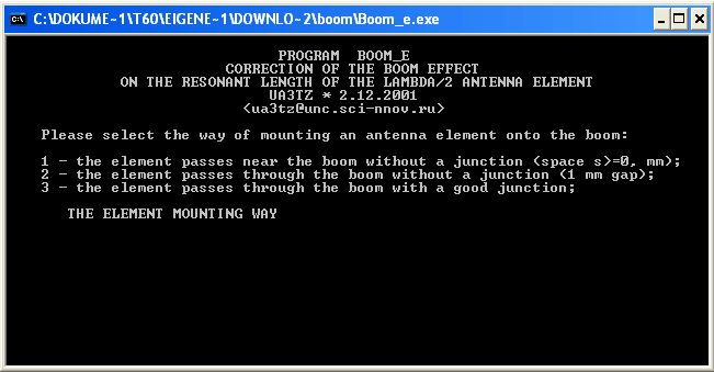
In contrast to most known corrections it also takes into account the distance to a boom end for elements mounted on the boom. Its output is a non uniform BC per element like we see with BC.exe by SM5BSZ, which is determind for correcting elements mounted insulated through boom.
Example : 144 MHz 2.5 wl Yagi, non uniform Boom Correction according UA3TZ
This is 4 mm elements mounted insulated through a 20 mm boom, first & last element at 20 mm from boom end. Note the dependency of BC number per element to its mounting position from boom end (this looks almost same in shape, with different numbers though in SM5BSZ BC.exe, see next chapter)

Link to external website with UA3TZ's article about this Boom Correction
It handles 3 types of element mounts:
Working with boom-e.exe
• Choose type of element mounting style 1, 2 or 3 style & enter
• Fill in element diameter & enter
• Fill in boom diameter & enter
• Fill in distance to nearer boom end & enter
• Fill in space between booms upper face and element (#1 on boom elements only) & enter

For next element type "1" for option '1 - other data' and proceed
Download Link to external download website www.radioscanner.ru
The program is enclosd in two languages
boom-e.exe = Version in English Language
boom-r.exe = Version in Russian Language
Tnx to Vladimir, UR5EAZ, who introduced this program to me
Comparing SM5BSZ BC.exe and UA3TZ boom(-e).exe
Example: Elements mounted insulated through boom
432 MHz - Influence of approaching the ends of the boom tube computed with BC.exe by SM5BSZ and boom(-e).exe by UA3TZ. Filled into the chart is the correction of 340 mm long elements in millimetres for a 20 x 20 x 2 mm square and Ø 20 mm round boom. Elements are of 4 mm in diameter. Elements lengths are frozen at 340 mm each to show a comparable set of numbers at varying distances to the nearer boom end.
The insulator holes in the boom of Ø 6 mm may ressemble nylon rivets (DL6WU/DJ9BV) or plastic bore hole end plugs (7YBN).

Comparing DG7YBN On-Round-Boom and UA3TZ boom(-e).exe
For this test I used a 30 mm round boom, 8.0 mm elements, 1.8 mm clearence between element and booms face
and a variety of distances for the 'distance to boom end' sensitive boom.exe

to the lenght the element is covered) and M3 screw through element and boom.
Non Uniform BC on all Elements & Boom Ends Influence
In the experts chats on moon net and elsewhere we note a great interest in if a BC needs to be adaptive to the element length. In my opinion we have to separate two causes her, since there are two mechanisms at work that degrade BC numbers on far out elements.
1. Insulated thru boom BC only
The BC.exe by SM5BSZ for insulated thru boom element mounting shows us that here there is a dependance of BC as function of distance to the nearest boom end. Just to give some orientation numbers: On a round 25 mm boom at 144 MHz the maximum decrease of BC is approximately 25% . Degradation starts very gently at a distance to the end of approximately 1 λ . Then falling rapidly when approaching the end.
144 MHz, round 25 mm boom, a coarse example only!
Standard BC of elements in mid of boom is 4.5 mm

Dist. to Boom End       BC decrease
1.000 λ                 0.01 mm
0.150 λ                 0.20 mm
0.014 λ                 1.10 mm
Expressed in maths like decrease dBC = 0.22 ln(distance to end) + 2.9), numbers in millimetres. Of coarse all much depending on boom tubes inner diameter, frequency etc. ... see BC.exe, above.
The mechanism at work is that the little piece of element enclosed in the boom tube radiates to a fraction of what radiates outside. The booms inner space acts as a cavity, with different influence towards the boom ends. This is the reason, why BC.exe has the inner boom diametre enclosed in its parameter set as 'wall thickness'.
Example 1: 432 MHz 19 Elem. Yagi (GTV 70-19m) - Influence of approaching the ends of the boom tube computed with BC.exe by SM5BSZ. Filled into the chart is the correction of the elements in millimetres for a 20 x 20 x 2 mm square boom. Dipole and elements are of 4 mm in diameter. The insulators are nylon rivets (DL6WU/DJ9BV) or plastic bore hole end plugs (7YBN) with 6 mm holes in the boom. On display is the superposition of the parameters (a) "Influence of nearer end of boom" and (b) "Length of the element".

Example 2: 432 MHz - Influence of approaching the ends of the boom tube computed with BC.exe by SM5BSZ. A fictitious sample to show the dependency of correction number applied to the element length to the distance to the nearer end of a boom. Because the element length is a parameter in BC.exe as well, the elements lengths are frozen at 300 mm each to show a comparable set of numbers at varying distances to the nearer boom end.
Example 3: 432 MHz Yagi Elemente - Influence of element length on correction number with sufficent distance to booms ends. Also computed with BC.exe by SM5BSZ. Filled into the chart is the correction of the elements in millimetres for a 20 x 20 x 2 mm square boom. The insulators are nylon rivets (DL6WU/DJ9BV) or plastic bore hole end plugs (7YBN) with 6 mm holes in the boom. On display is the alternation of the correction number over a variation of element lengths as parameter at a virtually fixed position on (.. through ..) the boom tube
2. All types of mounts
Same as mentioned according the form of the decrease will appy to the outside of the ending tube. Just on far less distance. An element nestling als very first or last close to a boom end will see much less Boom when the boom is cut sharply behing the element position. So that it sees almost only half of the amount of boom volume present Since aware of that we have cut all Test-Yagi booms for the On Boom BC with 30 to 40 mm excess length on first and last elements position. The published analyser plots show that this was a good idea and the right thing to do. If the exact correction is known one can resign from adding that excess lengths to the boom but shorten the BC on the far elements. The SM5BSZ BC.exe seems to encloses this mechnism too.
Microwaves conductive through boom
Boom Dim.       1296 MHz      2320 MHz
10 x 10 mm        n.a.         8.0 mm      DC3XY, DL6WU-Yagi for 2320 MHz, Dubus 4/1989
15 x 15 mm      11.0 mm         n.a.       DJ9BV, DL6WU Yagis for 23 cm, Dubus 2/1994
20 x 20 mm        n.a.          n.a.
Traditionally the elements are driven into the boom with a hammer to achieve a press fit - which must be protected
from corrosion by painting with clear coat.
Further Details
1. In DJ9BV's - "DL6WU Yagis for 23 cm" - Dubus 2/1994 we find Ø 4 mm elements made from aluminium AlMgSi1
to be pressed into a Ø 3.9 mm hole in a Ø 15 mm boom.
2. In DJ9YW's - "A Homebrew Yagi for 1296 MHz DX" - Dubus 1/2006 we find Ø 3.2 mm elements made from
aluminium AlMg5 to be pressed into Ø 3.1 mm holes in a square 15 x 15 x 1 mm boom.
3. In DC3XY's - "DL6WU-Yagi for 2320 MHz" - Dubus 4/1989 we find Ø 2.4 mm AlMg3 elements pressed into
Ø 2.3 mm holes in a square AlMgSi 10 x 10 x 1 mm boom.
Don't try this at home ... unless you absolutely stick to the data and geometries given in the above articles. Despite a more or less proven BC is given here, I advise not to be overoptimistic. For good reasons the mentioned designs are of very forgiving DL6WU style. Do not try this on a high Q-factor designs unless you are very skilled in building and measuring Yagis plus have at least a network analyser that covers the foreseen GHz band at hand.
Alternatively elements can be placed in a secure height above boom using offset insulators, as seen on the 1296 and 2320 MHz Tonnas and I0JXX.
Note that the NEC2 manual holds a passage where it states that at very high frequencies well above 432 MHz a tube end may have the effect of a small capacity against that of a solid rod. Thus a tube elements electrical lengths will be inflicted by this. Numbers given are a vague as this. But I thought this to be worthwhile to be forwarded in this context.
What may obscure right BC measures
The Yagi may be divided into three zones
  1. Driver Cell
  2. Wave guiding structure
  3. Take off zone
To complete the package forming the impedance and reactance we measure at the feed point we have to add
4. Symmetrising and transforming membersMost of the common symmetrising and transforming members are made from coax cable.
1. Getting the coax cutting done right
Attenzione!
It is understood that a length of coax cable needs to be shortened using its velocity factor if we want to cut a resonate
length. A waves speed in a medium is described as

According IEC 60250 the dielectrical constant εr of (natural) PTFE is 2.1, measured at 1 MHz equalling v = 0.690 = 69%. However Radio Amateurs mostly use v = 0.7... 0.71 so that the calculated length of a 144 MHz Quarter Wave Line is around 369 mm.
But have you ever measured the resonance frequency what you have cut? At VHF and above you will probably be surprised to find your stub being some 5...10% too low in resonance frequency. This is due to εr and v-factor being specified at a much lower frequency and plastics dielectrical properties are frequency depending to a certian extend.
From left to right: DK7ZB match, λ/2 Balun, Quarterwave line


The full story is that plastics hold a so called Dynamic Dielectrical Constant.
    M. Bonnet, Kunststoffe in der Ingenieuranwendung, Vieweg + Teubner, Wiesbaden 2009, pg. 73
    Chapter 1.7.1.3 Dynamic Dielectrical Constant and Dielectrical Loss

    My translation from original German text:

    'In an alternating electrical field the electrical dipoles [of the plastic]
    are forced to oscillate with frequency ν of the alternating field. Molecules
    with orientation polarisation are hereby constantly forced to alter their alignment
    in the volume. This leads to relaxation damping.'
It is said relaxation damping that degrades the dielectrical constant with increasing frequency, which lowers the wave speed in the plastic. That makes our velocity factor drop - and so needs our coax stubs length at VHF and above. Eventually measuring and tuning in the exact length of your VHF/UHF coax balun or quarter wave lines is a must if it shall be precise. Not to mention the influence of all connecting open coax ends.
Find more information on Phasing & Matching Lines page
2. Why is an exact length of the coax balun or quarter wave line that important?
Any excess length of our matching network will virtual add to the Driven Elements span width. Example: A quarter wave line for 144.1 MHz made from PTFE coax RG-142 B/U has a length of 369 mm when calculated using the commonly used v-factor of 0.7. The lines length when carefully tuned to resonace as a quarterwave line at 144.1 MHz with aid of a Network Analyser is 345 mm. The 24 mm or 7% of excess length will affect the VSWR we measure on the complete arrangement of the Yagi plus matching network.
Read more about the outcome of such imperfections in my article 'Applied Conversion of Segmented Wires from NEC to 144/432 MHz Yagi Elements - Part 3' in Dubus 2/11.
Boom Correction and NEC Models Segmentation
What happens if we vary the segmentation density of the Elements (Wires) in a NEC model?
We see the impendance resonance peak shift in frequency. The three plots below show the same 2m Yagi. Just with increasing segmentation density from one Return Loss plot to the next plot. The Numbers given show stepped segmentation densities, wherein the reflector uses most segments (starting number) and running along the elements getting less as length drops until we reach the last direction parasitic element. That way each segment is of almost same length, which results in best model accuracy we can get from NEC.
5 elem. DUT Yagi => 11 ... 9 segments (EZNEC Auto Segmentated at 144 MHz)

5 elem. DUT Yagi => 16 ... 13 segments (EZNEC Auto Segmentated at 220 MHz)

5 elem. DUT Yagi => 24 ... 20 segments (EZNEC Auto Segmentated at 340 MHz)

5 elem. DUT Yagi => 43 ... 36 segments (EZNEC Auto Segmentated at 620 MHz)

What RL plot will representate the true plot shape for a boomless build as base for adding a BC?
Deriving the SBC component
It is of vital importance to find the fitting segmentation density that corresponds with your kind of antenna - or better said - the way the applied NEC kernel deals with the challenges enclosed in the very model. To enclose the influence of models segmentation in the BC theory I have introduced the 'Segmentation BC' (SBC) component. Actually it is not a BC challenge by classical means. Traditional BC numbers are meant to be applied on a Yagi that is exactly on frequency as a boomless real world build.
The SBC will help in converting wires from NEC to real world builds. This additional SBC bridges over from not fitting segmentation densities to a corresponding with boomless builds densities by determinating the gap in both models resonace peak frequencies. The difference in frequency is equal to an extra portion of BC in millimetres.
In doing so the SBC does what is often not realised when applying likewise DL6WU/G3SEK BC numbers on whatever model and expecting the ingenuity of DL6WU to solve all challenges.
Run your model twice. Once with segmentation density as designed with, note resonace peak frequency. Do a second run with boomless builds density, note that frequency too. Calculate the delta in frequency. Multiply by factor given in table below to gain the SBC in millimetres which must be added to the common BC.
How does it occure and what sign must the SBC's correction length have?
Here we have to think out of the box [Dt: "um die Ecke denken"]. A designer is convinced that a segmentation density somewhat higher than what would represent the actual boomless build is a good choice. So he designs his Yagi with the consequence that by using the higher segmentation density an element of same length will virtually appear longer to the NEC Kernel that at true density applied. Consequently he will shorten all elements in his NEC model by that amount in order to end up with a model simulation resulting in the seeked frequency as resonace peak. Simulating this design using the corresponding to boomless build segmentation will derive a higher in frequency resonance peak. The real world build would be too high by that amount. This we neutralise by adding the right SBC in millimetres. In the opposite case of a Yagi designed with less segments that corresponding to boomless build the amount will have to be subtracted.
The SBC ...... a Segmentation Density (Boom) Correction
The SBC covers different segmentation numbers used on individual designs or by individual designers for best conversion of the NEC geometry into numbers for a real world build in addition to applying the common BC to adapt to an individual style of building and boom dimensions.
How to apply?
| The SBC is simply added to the ordinary Boom Correction |
|
What numbers to use?
Both, boomless builds segmentation density and factor to transform the SBC to millimetres must be derived by measurements on real builds. For a conventional Yagi by means of a straight split DE and no quad style or sharply bent parasitc elements the corresponding to a boomless builds segmentation density is very close to what you get using EZNEC's auto segmentation function at the antennas designated frequency. That is around starting with 11 at the reflector and going down to 9 segments for the far out directing elements. For a Yagi with loop fed Driver Cell like the G0KSC LFA this is around 30+ segments, this equals what you get when using EZNEC's auto segmentation function at around 420+ MHz.
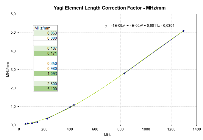
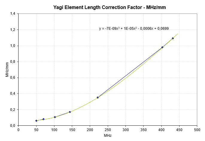
Multiplication factors for deriving the SBC in millimetres
Freq. [MHz]     Factor [mm/MHz]
    50               16.00        (provisional)
    70               12.50        (provisional)
   144                5.85
   222                2.86        (provisional)
   403                1.02        (provisional)
   432                0.92
  1296                0.196
(numbers above are just the reciprocal values of what I
have published in the Dubus BC-Series Articles in MHz/mm)
An Example:
A highly segmented 144 MHz Yagi Design shows best simulated RL on 144.3 MHz,
Auto Segmented at 144.1 MHz => simulated best RL shifts up to 144.7 MHz
SBC = delta freq. * Factor = 0.4 MHz * 5.85 mm/MHz = 2.3 mm
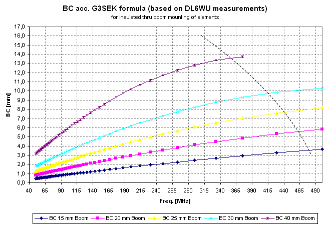
Overview: Yagi element length correction numbers per MHz/mm in a chart
basically tested fully tested
Overview: Yagi element length correction numbers per MHz/mm in a chart - 0 ... 500 MHz
Overview: Yagi element length correction numbers per invers value mm/MHz in a chart

If we do not enclose the SBC but trim a Yagi designed using a high segmentation density to wanted frequency
by manipulating DE and D1 ... at the end of the day we might get the Yagi to have its VSWR low where we want it to
be finally. But the directing parasitic elements and reflector will fall short by the amount of SBC. So that by this, plus the
manipulation done to the Driver Cell neither radiation pattern nor whatever data from gain to F/B or antenna temperature will be
exactly as designed.
Some Permittivity Numbers
Material     at        1 MHz       3 GHz

Beewax                  2.53       2.39
Silicone               11.7-12.9
Silicone RTV            3.6
Rubber                  3.0-4.0
Butyl Rubber            2.35       2.35

ABS                     2.0-3.5
Bakelite                3.7
Delrin (R) resin        3.7
Kapton (R)             3.9 - 2.9
Nylon                  3.2 - 5
Acryl glass            2.2-3.4
LDPE & HDPE            2.26        2.26
PA                     2.5-2.6
Polycarbonate          2.8-3.4
PP                     2.2
PVC                    3
PTFE                   2.0-2.1


Epoxy PCB               5.2
FR4 PCB                 4.9        4.2
RT PCB                  2.2

Water                 ~ 80 at 20 C
Ice (de-ioned Water)    4.15        3.2
DG7YBN Yagi Element Configuration Tool
Since Version 1.32 this Tool has an own website: click here
This MS Excel Tool is the follow up of my On-Boom-BC Excel. Current Version No. is 1.51

DG7YBN Yagi Element Configuration Tool, Vers 1.51
Key features
• Computes BC according DL6WU, SM5BSZ and DG7YBN for Elements insulated on Boom
• Amateur Bands 50 to 432 MHz
• NEC file import from 4nec2
• Data base that can be imported / exported to CSV format
• Basic beta-version of a Yagi windload calculator
• It is tested with MS Excel 2003 on winXP, MS Excel 2007 on winXP, MS Excel 2010 on win7
Sorry win98, win2000 and MS Excel from the 97 MS Office are not supported.
Neither will any 64 Bit Excel run all features - several runtime to debug scenarios are known.
A 64 bit OS itself is no problem but the 64 bit Excel is.
However, your MS Excels Safety Settings must be set to enable Macros since this Calculator
holds in excess of 8000 lines of Visual Basic Code.
Disclaimer: this Excel contains macros.
Use only downloads from a safe source; Use is at own risk whatsoever (!)
To download the zipped tool go here
Note: The logos, notations, brands and trade names shown or mentioned on this website are the property of the
correlating companies and are subject to trademark rights !
73, Hartmut, DG7YBN