
-
• Main Page
- • Home
• Antennas - • 432 MHz
- YBN 70-5mA 0.5 m 432 MHz blue print of the YBN 2-5m 50 ohms high F/B direct feed 144 MHz Low Noise Yagi
3D Plot
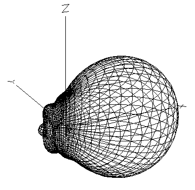
- YBN 70-8zA 1.5 m high gain 28 ohms Yagi.
A design partly based on the hardware of the WY-7010, turning it into a 8 ele. 28 ohms Yagi with cleaner pattern, +1.8 dB gain and better VSWR.
Azimuth Plot
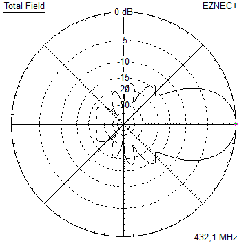
- YBN 70-14wzTune up your 19 ele. Tonna!
A design based on the hardware of the F9FT, turning it into a 14 ele. OWL with cleaner pattern, +0.3 dB gain and SWR less than 1.2 from 430 to 440 MHz
Azimuth Plot
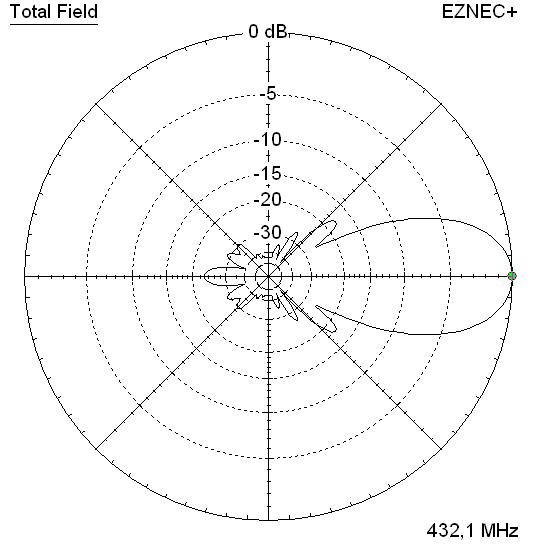
- YBN 70-14+4wA 3.2 m very wideband 50 ohms Yagi with reflector wall that covers the whole 70 cm band with ease
Elevation Plot
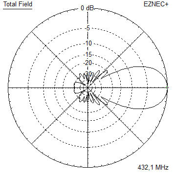
- Mod. WY7023Modification for the WiMo WY7023
A design based on the hardware of the WiMo WY7023, turning it into a 21 ele. OWL with bent dipole (K6STI style), much cleaner pattern, +1.4 dB gain, SWR < 1.2:1 from 430 to 438.7 MHz
Elevation Plot
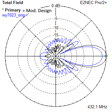
- GTV 70-2wA 0.14 m GTV useful for portable operation and up to the satellit band and handheld activities of any kind
Elevation Plot
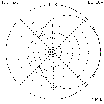
- GTV 70-3wA 0.21 m GTV useful for portable operation and up to the satellit band and lower noise stacks of any kind
Elevation Plot
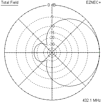
- GTV 70-4wA 0.33 m wideband GTV useful for portable operation up to the satellit band and lower noise stacks of any kind
Elevation Plot
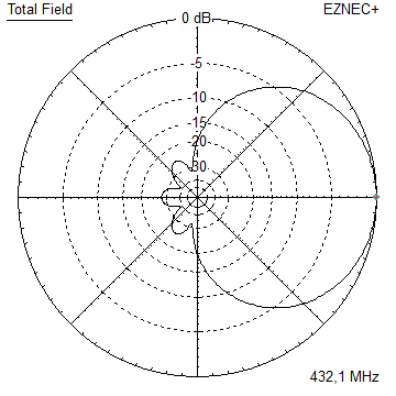
- GTV 70-4mA 0.34 m GTV useful for portable operation up to the satellit band and lower noise stacks of any kind
Elevation Plot
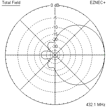
- GTV 70-6mA 0.79 m GTV useful for portable operation and lower noise stacks of any kind
Elevation Plot
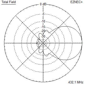
- GTV 70-7wA 0.96 m GTV useful for portable operation up to the satellit band and lower noise stacks of any kind
Elevation Plot
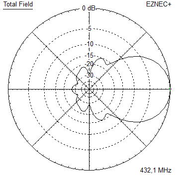
- GTV 70-7nA 1.1 m 432 MHz blue print of the low impedance, yet 50 ohms direct feed 144 MHz Low Noise Yagi introduced in Dubus 1/2013
Elevation Plot
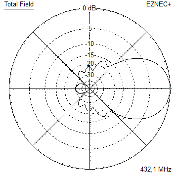
- GTV 70-8nA 1.3 m 432 MHz GTV with high gain but low backlobe volume. Makes a very compact 4 Yagi bay for QRP EME or contesting.
Elevation Plot

- GTV 70-9wA 1.44 m GTV ment to be useful as a vertical stack for contesting or be an ideal small size portable Yagi
Elevation Plot
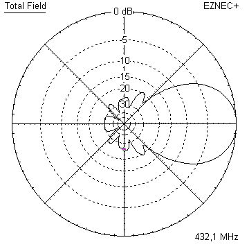
- GTV 70-10wA 1.63 m GTV useful for portable operation up to the satellit band and lower noise stacks of any kind
Elevation Plot
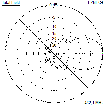
- GTV 70-11wA 2.01 m GTV ment to be useful as a vertical stack for contesting or be an ideal small size portable Yagi or minimum size EME 4 bay
Elevation Plot
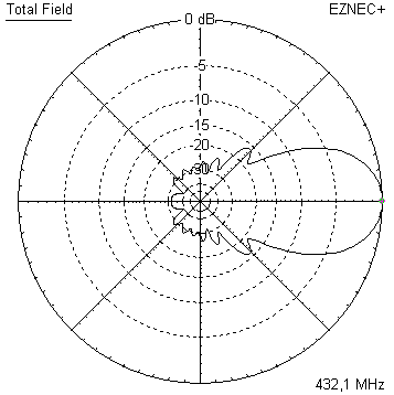
- GTV 70-13mA 2.5 m GTV ment to be useful as a vertical stack for contesting or be an ideal small size portable Yagi or minimum size EME 4 bay
Elevation Plot
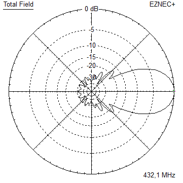
- GTV 70-14m2.9 m version of the low impedance, yet 50 ohms direct feed Low Noise Yagi with bent DE introduced in Dubus 1/2013
Elevation Plot
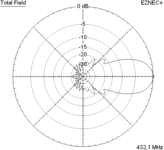
- GTV 70-17m3.7 m version of the low impedance, yet 50 ohms direct feed Low Noise Yagi with bent DE introduced in Dubus 1/2013
Elevation Plot
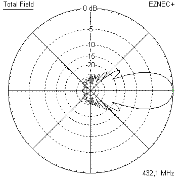
- GTV 70-18w4.0 m version of the low impedance, yet 50 ohms direct feed Low Noise Yagi with bent DE introduced in Dubus 1/2013
Elevation Plot
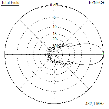
- GTV 70-19m4.2 m version of the low impedance, yet 50 ohms direct feed Low Noise Yagi with bent DE introduced in Dubus 1/2013
Elevation Plot
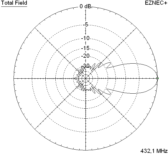
- GTV 70-21n4.7 m version of the low impedance, yet 50 ohms direct feed Low Noise Yagi with bent DE introduced in Dubus 1/2013
Elevation Plot
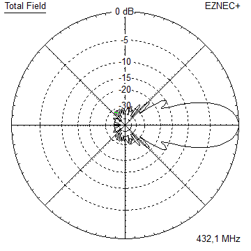
- GTV 70-23m5.3 m version of the low impedance, yet 50 ohms direct feed Low Noise Yagi with bent DE introduced in Dubus 1/2013
Elevation Plot
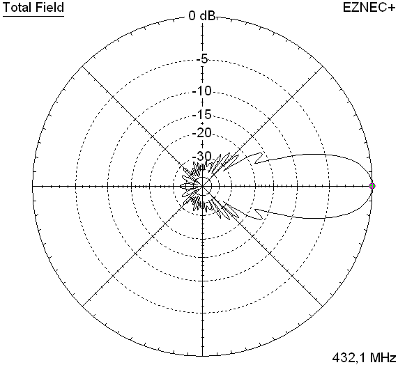
- GTV 70-25m5.9 m version of the low impedance, yet 50 ohms direct feed Low Noise Yagi with bent DE introduced in Dubus 1/2013
Elevation Plot
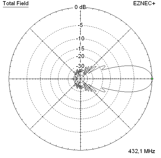
- GTV 70-30m7.3 m version of the low impedance, yet 50 ohms direct feed Low Noise Yagi with bent DE introduced in Dubus 1/2013
Elevation Plot
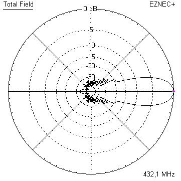
- GTV 70-34w8.5 m version of the low impedance, yet 50 ohms direct feed Low Noise Yagi with bent DE introduced in Dubus 1/2013
Elevation Plot
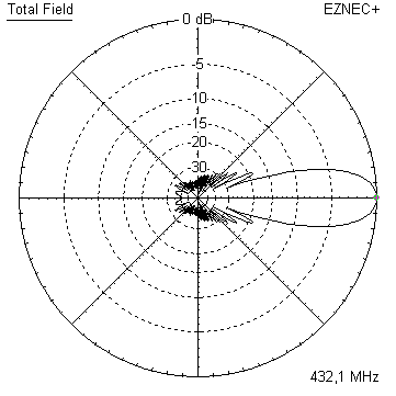
- GTV 70-46w12.0 m version of the low impedance, yet 50 ohms direct feed Low Noise Yagi with bent DE introduced in Dubus 1/2013
Elevation Plot
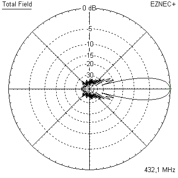
- DL6WU YagisThe DL6WU Longyagi Series
Sample plot: 32 el. plus 4 x reflector
Elevation Plot

- YBN 70-5m
 Analysis - Performance Data
First Aid: WiMo WY7023 mod. Phase 1 Stacking for the WiMo WY7023 mod. Phase 1 Matching for the WiMo WY7023 mod. Phase 1
WiMo WY7023 Yagi with folded dipole
WiMo advertises the WY7023 in their interent shop as follows:
Source: www.wimo.com/en/wimo-wy-uhf-yagi-antenna
• Highest possible gain with high bandwidth and good side lobe and return loss. Thus the antennas are oriented to the requirements of serious VHF amateurs, who need a high performance antenna for long distance traffic and all modes of operation. The design principles of the Yagis were worked out with computer programs calibrated at NEC and verified by many test setups.
• Design current optimized (...). The yagis were designed for an optimal current profile. In older designs, there are jumps in the element current assignment, resulting in underutilized gain and poorer side lobe and return loss.
All this is clearly fine for the 2 m series of Yagis improved by DK7ZB, just not for the WiMo 70 cm series of 6, 10, 18 and 23 element Yagis. WiMo to the date of issuing this website (2026-10-30) does not provide radiation pattern plots for the WY7023.
Origin of the design?
The design of the WY7023 is twinned with what we find in Karl Rothammels (DM2ABK) Antennenbuch, Militärverlag der DDR, 8th issue, 6/1974: "Eine 18-Element-Breitband-Lang-Yagi", pg. 394, 395, fig. 24.8. The origin seems to be Spindlers Antennenbuch; Eberhard Spindler, VEB Verlag Technik Berlin, from 1968 ... . The directing element chain shows a relation to the NBS-Yagi with 0.308 lambda of spacing, see Peter P. Viezbickes 'NBS Technical Note #688', Yagi Antenna Design, 12/1976, therein table 1: 3.2 wl Yagi. This clearly is a pre-DL6WU design (inhomogeneous spacings, see DL6WU: Wirkungsweise und optimale Dimensionierung von Yagi-Antennen, UKW-Tagung, 1976).
Open a scan of the page in Rothammels Antennenbuch here
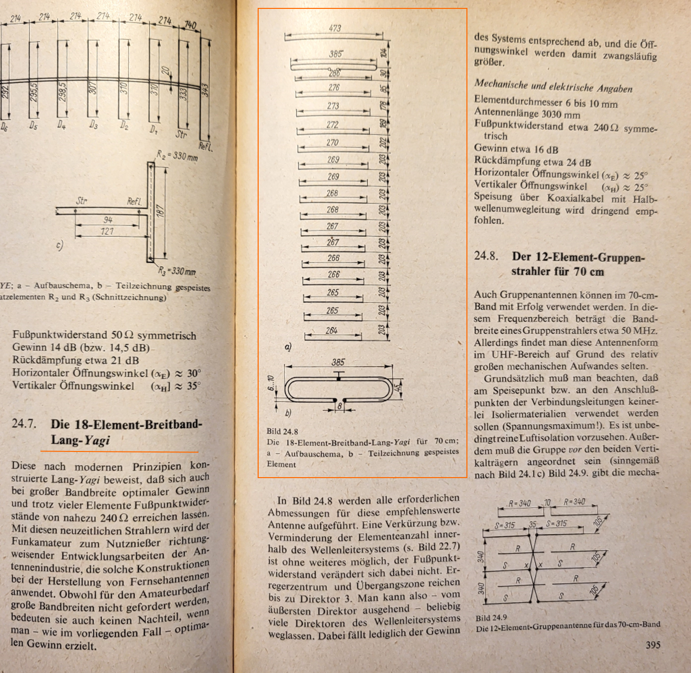 .
In Rothammel it is spoken of modern design principles for long Yagis (1974), pioneering development work in the antenna industry, which uses such constructions in the manufacture of television antennas. 'Although wide bandwidths are not required for amateur radio use, they are not a disadvantage either if, as in this case, optimal gain is achieved.' (Which from todays point of view is, say quite debatable, as the Yagi as is, misses approximatly 1.5 dB in gain alone for its length).
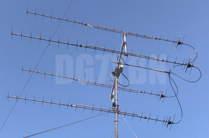
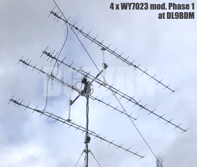
In early August of 2026 Eilert, DL9BDM asked me if I would have a pattern plot diagram of the WY7023, which I had not. Eilert had 4 of these Yagis in H-config on the mast and was bothered about their performance. Frankly, he purchased a 5th and measured the geometry. I subtracted the boom correction and simulated the design in EZNEC Pro2+ v.7.0.
Date of issue: 2026.08.15 .
4 x WY7023 at DL9BDM:
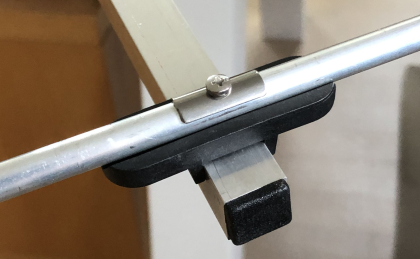
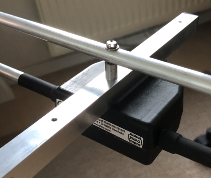

Analysis / Simulation
Current distribution WY7023
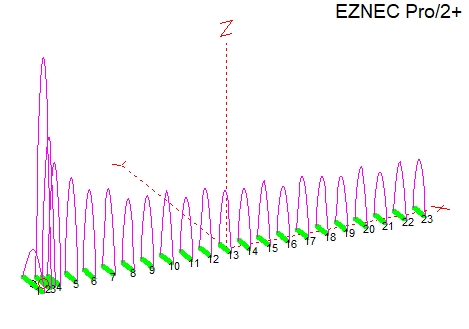

With a fix element distance of 203 mm equal to 0.29 lambda from D5 all the way to D21 it cannot be current optimised, contrary to the manufacturers advertise text.
Quote from the WiMo website:
The yagis were designed for an optimal current profile. In older designs, there are jumps in the element current assignment, resulting in underutilized gain and poorer side lobe (...).
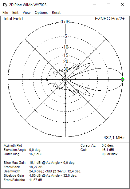
Pattern at 432.1 MHz
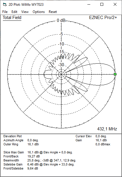
At above 440 MHz, due to D1 to D5 or 6 or 7 being too short for 432 MHz, the Yagi finally comes to terms. But then the last 8 or 5 elements are too long:
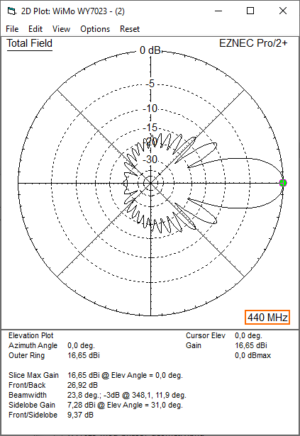
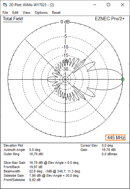
Specs: with 8 mm elements @ 432.1 MHz
Gain vs. isotr. Rad.  16.1 dBi
Gain vs. Dipole       14.0 dBD vs. '15 dBD' per WiMo description *
-3 dB E-plane         24.8 deg.
-3 dB H-plane         25.8 deg.
F/B                  -19.3 dB
F/R                  -17.8 dB
Impedance               50 ohms (200 Ohms + half wave line)
Mechan. Length        4035 mm plus boom end offsets
Electr. Length        5.82 λ

Stacking dist. h-pol. (100 percent per DL6WU)
top-to-bottom         1.440 m
side-by-side          1.560 m
*) A medium quality to date design delivers a gain of approximately 15.4 dBD on 4.0 m boomlength.
How many OMs have been looking up this design since Oct. 2026?
G/T analysis with AGTC Twain-JS: 4 bay of original WiMo 7023 modelled with folded dipole, at 432.1 MHz, at 100 percent of Dopt per DL6WU:

First Aid
Modification Phase 1
WY7023 mod. ph.1 by DGYBN. Date of design issue: 2026-10-304 x WiMo WY7023 mod. Phase 1 by Eilert, DL9BDM
WiMo WY7023 mod. Phase 1, Current distribution and Modification Scheme
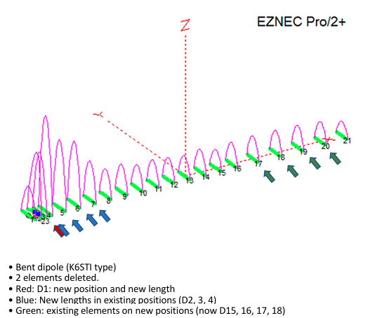
The in between turmoil is due to sparing D6 to D14 in this phase 1 modification.
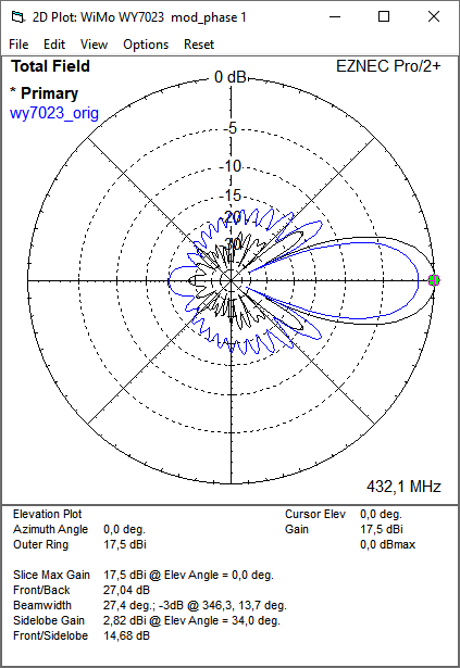
Radiation Pattern at 432.1 MHz
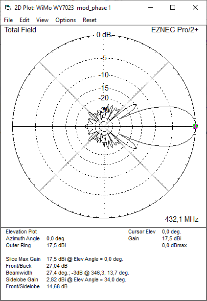
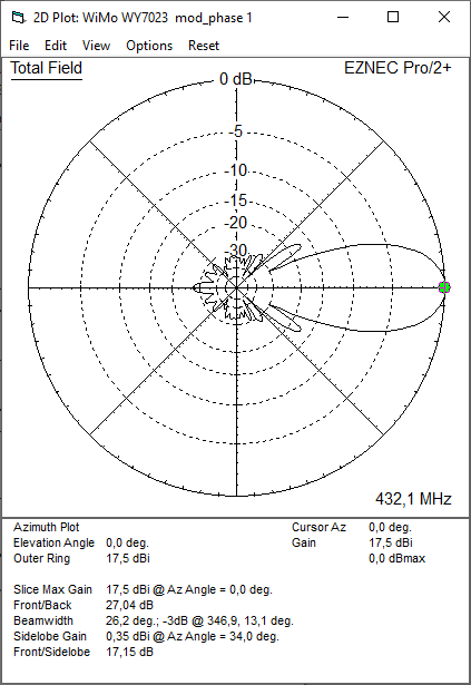
Specs: with 8 mm elements @ 432.1 MHz
Gain vs. isotr. Rad.  17.5 dBi vs. '16.1 dBi' of the original WY7023
Gain vs. Dipole       15.4 dBD
-3 dB E-plane         26.2 deg.
-3 dB H-plane         27.4 deg.
F/B                  -27.0 dB vs. '-19.3 dB'
F/R                  -26.9 dB vs. '-17.8 dB'
Impedance               50 ohms (200 Ohms + half wave line)
Mechan. Length        4035 mm plus boom end offsets
Electr. Length        5.82 λ

Stacking dist. h-pol. (100 percent per DL6WU)
top-to-bottom         1.465 m
side-by-side          1.531 m
Bent Dipole: DE(a) is the inner straight length and pos. on boom, DE(b) is position of tips and span width when bent
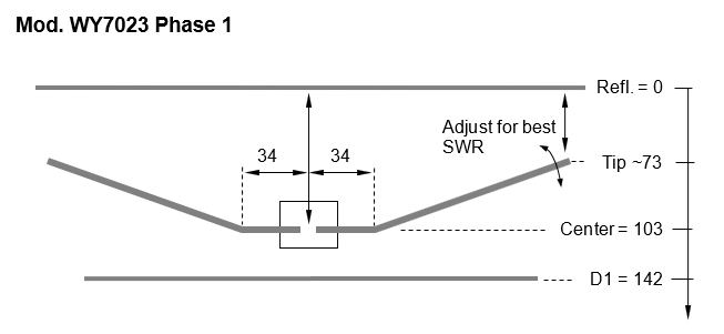
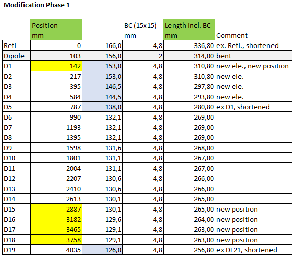
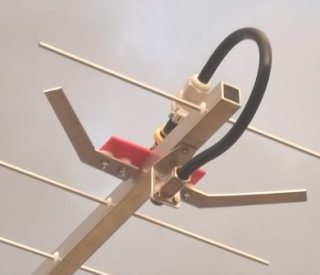
Driver cell and bent dipole (K6STi style) by DL9BDM:
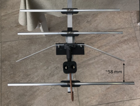
Dipole arms made from 15 x 2 mm aluminium strips: width ~299 mm.
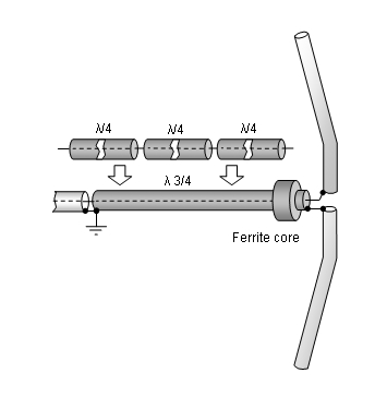
A simple symmetrising section may be made from a 3 x 1/4 Lambda line grounded at the far end with
N-flange-bushing and an aluminium plate and ferrite core added as close as possible to the DE,
see below.
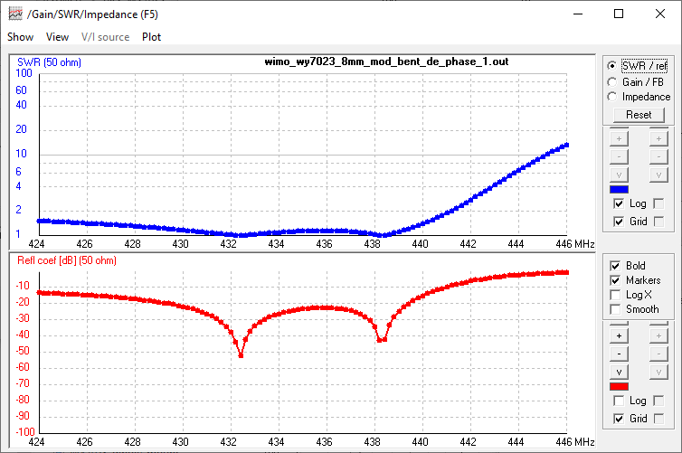
WiMo WY7023 mod. Phase 1, VSWR and Return Loss
Comparison of Elevation Patterns: Original WY7023 and Modification Phase 1
WiMo WY7023 mod. Phase 1, Stacking
Stacking Dist. at 100 percent of Dopt per DL6WU Formula
H-plane               1.465 m
E-plane               1.531 m
WiMo WY7023 mod. Phase 1, 4 Yagi array in H-configuration
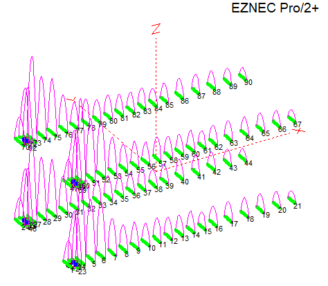
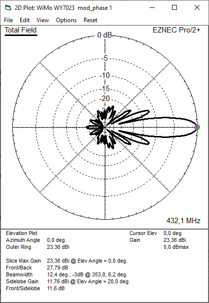
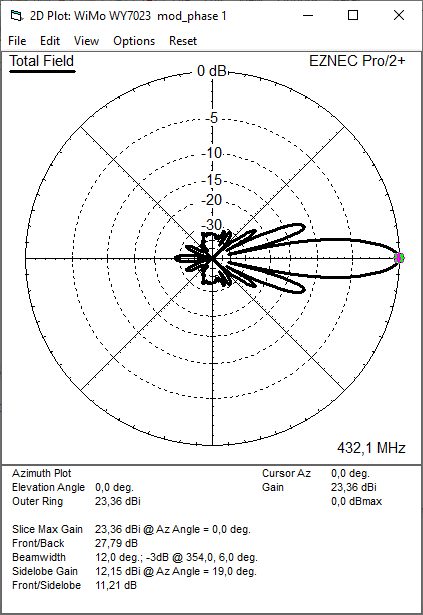
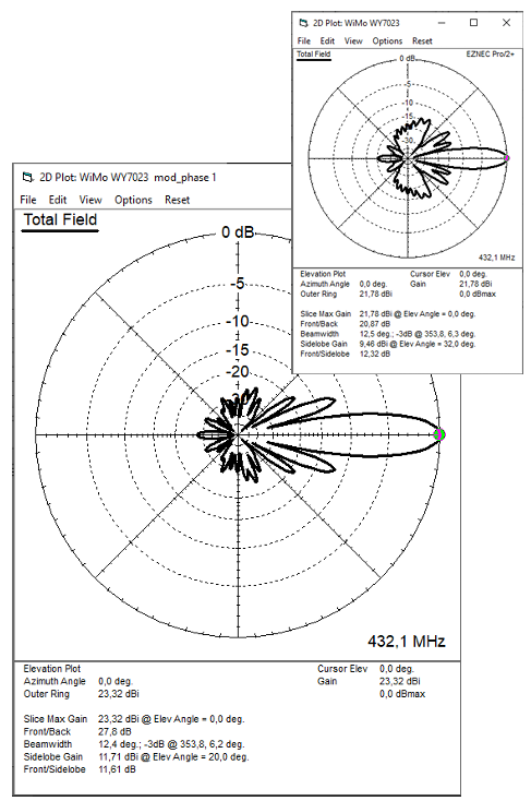
Elevation and azimuth plot and data of 4 Yagi bay using DL6WU stacking distances
Data (8 mm el. and at 432.1 MHz, at 100 percent of Dopt per DL6WU)
Gain vs. isotr. Rad.  23.30 dBi vs. '21.8 dBi' of the original WY7023
Gain vs. Dipole       21.21 dBD
-3 dB H-plane         12.4 deg.
-3 dB E-plane         12.0 deg.
F/B                  -27.8 dB
F/R                  -27.8 dB
T_ant                 78.5 K*   vs. '293.2 K'
G/T                    4.35 dB* vs. '-2.89 dB'
Theoretical numbers - these do not include phasing line losses
nor imperfections caused by H-frames or mast poles etc.
*) T_sky = 27 K, T_earth = 1800 K as in newer VE7BQH G/T table
G/T analysis with AGTC Twain-JS:

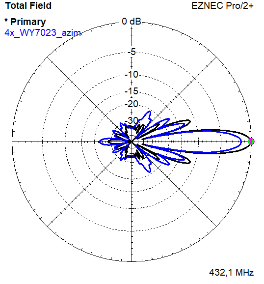
Comparison of Elevation Patterns:
4 x Original WY7023 and 4 x Modification Phase 1, both at 100% DL6WU stacking D_opt at 432.1 MHz;
Elevation plots on left, azimuth plots on right:
Symmetrising 50 to 50 ohms feedline to 432 MHz Bent DE
The principle is similar to the 1/4 Lambda coax. Adding 2 x 1/4 Lambda or a half wave line does not change anything but allows
to form a gentle bow below the boom or until behind the Reflector. Follow practical construction hints on "Building a Yagi" page.
Attenzione!
Take care when lengthening the coax, measure the actual electrical length instead of considering v-factors specified in a catalogue only.A good choice may be the diam. 5 mm PTFE coax RG-142 B/U: real resonate length (432.2 MHz as 3/4 Lambda) shield-shield is around 348 mm
 Find more information on Phasing & Matching Lines page
73, Hartmut, DG7YBN