-
• Main Page
- • Home
• Antennas - • 1296 MHz
- YBN 23-5mA short Yagi with straight dipole for the 23 cm band
Elevation Plots

- YBN 23-9mA short Yagi with straight dipole for the 23 cm band
Elevation Plots
- GTV 23-14wA 0.94 m bent dipole longyagi for the 23 cm band
Elevation Plots
- GTV 23-23mA bent dipole longyagi for the 23 cm band
Elevation Plots

- GTV 23-25mA bent dipole longyagi for the 23 cm band
Elevation Plots

- GTV 23-34wA bent dipole longyagi for the 23 cm band
Elevation Plots
- GTV 23-46wA 4 m bent dipole longyagi for the 23 cm band
Elevation Plots
- GTV 23-65wA 6.0 m bent dipole longyagi for the 23 cm band
Elevation Plots

- General Info23 cm Yagi building details and background info
-
- YBN 23-5m
GTV 23-14w Yagi with bent Driven Element (K6STI style)
A 0.94 m long 23 cm Yagi that provides a very clean pattern and 16.2 dBi of gain.
This is the scaled and adapted version of the 2 m band GTV 2-14w. Design date of issue: 2023.03.06

GTV 23-23m 3D pattern plot at 1296.2 MHz

Performance Data
Specs: with 3.2 mm elements @ 1296.2 MHz
Gain vs. isotr. Rad.  16.2 dBi
Gain vs. Dipole       14.0 dBD
-3 dB E-plane         29.8 deg.
-3 dB H-plane         32.5 deg.
F/B                  -32.5 dB
F/R                  -26.9 dB
Impedance               50 ohms
VSWR Band Width       1.05:1*
Mechan. Length        920 mm plus 2 x 50 mm offset
Electr. Length        7.55 λ

Stacking Dist. h-pol. (1296.2 MHz)
top-to-bottom         0.415 m or 1.39 ft
side-by-side          0.450 m or 1.48 ft

*) at 1300.0 MHz
How many VHF operators have been looking up this design since Oct. 2023?
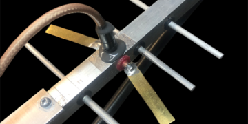
GTV 23-14w built by Holger, DF2FQ


Plots S11 and Gain here:
Geometry
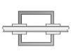
This Yagi with 3.2 mm elements (aluminium welding rods) electrically insulated through 15 x 15 mm boom,
positions for formast mounting
|
Boom shape: square Boom dim: 15 x 15 mm Wall thickn.: 1.0 mm Holes in boom: 5.2 mm Offset rear: 400 mm Offset front: 40 mm |
|
"Ready to saw and drill" data for mounting elements through this boom:

The Drivers diameter is 3.2 mm but should be made 5.0 mm and trimmed down to fitting length.
The insulators must have a fitting diameter for press fit in a 5.2 mm hole, insulator length is 7 mm, do not alter either dimension without consulting me.
The EZNEC model is done with Auto-Segmentation at 1296.2 MHz
This Yagi with 4.0 mm elements (aluminium welding rods) electrically insulated through 15 x 15 mm boom,
positions for formast mounting
|
Boom shape: square Boom dim: 15 x 15 mm Wall thickn.: 1.0 mm Holes in boom: 6 mm Offset rear: 280 mm Offset front: 50 mm |
|
"Ready to saw and drill" data for mounting elements through this boom:

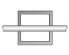
This Yagi with 4.0 mm elements (aluminium welding rods) pressed electrically conductive through a 15 x 15 mm boom,
positions for formast mounting
|
Boom shape: square Boom dim: 15 x 15 mm Offset rear: 400 mm Offset front: 40 mm |
|
"Ready to saw and drill" data for mounting elements through this boom:
Please note: This table holds the Boom Correction of 11.0 mm per DJ9BV as in his article "DL6WU Yagis for 23cm", Dubus 2/1994.
I have not tested this.

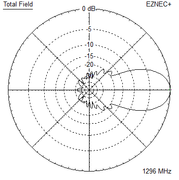
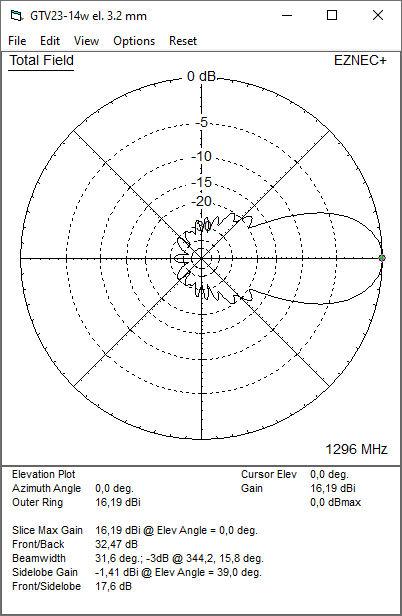
Pattern and VSWR Plots
Elevation and Azimuth plot at 1296.2 MHz

Return Loss and VSWR plots - simulated

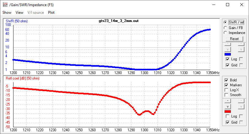
Return Loss and Gain plotted by Holger, DF2FQ

VNA: Agilent HP 8753E with ECal (Electronic Calibration Module),
Reference Antenna: R&S HL050;
Test range: 2 poles a 2.5 m, distance 14 m.
Gain is measured as S21 here with reference plains for both ports at the antenna feeds;
Path attenuation and antenna factor are corrected.
Measured: 15.85 dBi at 1296 MHz vs. 16.19 dBi in simulation.
GTV 23-14w build details: 4.00 mm ele., no BC or SBC, straight from EZNEC v5+ wires segmented at op.-frequency,
thin plastic holders for ele. over boom, see photo above.
Tnx Holger!
Downloads
None so far.
Stacking
Stacking Dist.    DL6WU Formula (144.3 MHz)
E-plane               0.415 m or 1.39 ft
H-plane               0.450 m or 1.48 ft
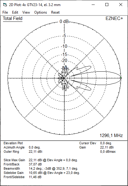
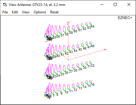
4 x GTV 23-14w in H-config. at distances per DL6WU:


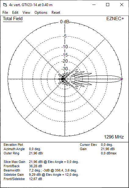
4 x GTV 23-14w vertical at 400 mm each:


73, Hartmut, DG7YBN