-
• Main Page
- • Home
• Antennas - • 1296 MHz
- YBN 23-5mA short Yagi with straight dipole for the 23 cm band
Elevation Plots

- YBN 23-9mA short Yagi with straight dipole for the 23 cm band
Elevation Plots
- GTV 23-14wA 0.94 m bent dipole longyagi for the 23 cm band
Elevation Plots
- GTV 23-23mA bent dipole longyagi for the 23 cm band
Elevation Plots

- GTV 23-25mA bent dipole longyagi for the 23 cm band
Elevation Plots

- GTV 23-34wA bent dipole longyagi for the 23 cm band
Elevation Plots
- GTV 23-46wA 4 m bent dipole longyagi for the 23 cm band
Elevation Plots
- GTV 23-65wA 6.0 m bent dipole longyagi for the 23 cm band
Elevation Plots

- General Info23 cm Yagi building details and background info
-
- YBN 23-5m
YBN 23-9m Yagi with straight Driven Element
A short and easy to build 23 cm Yagi that provides a clean pattern and almost 14 dBi of gain.
This is the scaled version of the 2 m band YBN 2-9m. Design date of issue: 2020.12.29

Building of a 23 cm Yagi with elements insulated through the boom making use of
SM5BSZ's BC.exe on 1296 MHz with a tested offset factor as in full described in
'Applied Conversation of Segmented Wires from NEC2 to 1296 MHz Yagi Elements', Dubus 2/2021.
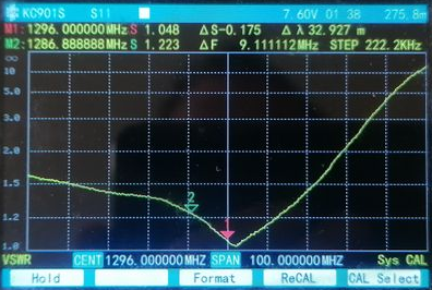
This Yagis S11: Return Loss (dB) plotted by ZS6JON with an Anritsu MS2000 VNA:
For the geometry table of the YBN 23-9m through a 5/8 inch boom see here

YBN 23-9m pioneer build by Maxime, F4FEY (thanks Maxime!).
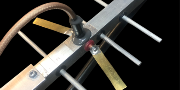
The Yagi is build on Boom 7.5 x 7.5 mm ABS Plastic using 3 mm elements and 4 mm dipole.


YBN 23-9m build by Ondra, OK1CDJ
The Yagi is build on 3D printed boom, material is PETG.

YBN 23-9m build by Rainer, DK1RS
The Yagi is build on 3D printed boom, 3.2 mm elements made from AlMg5 welding rods.


YBN 23-9m build by DF3FX (thanks Felix!).
The Yagi is built on a 25 mm "Isolationsrohr EN 25" from PVC.
Element diameter is 3.2 mm. Material = welding rods EN ISO 18273, S AlMg 5754 (AlMg3), 3.3536.


YBN YBN 23-9m 3D pattern plot at 1296.2 MHz

Performance Data
Specs: with 3 mm elements @ 1296.2 MHz
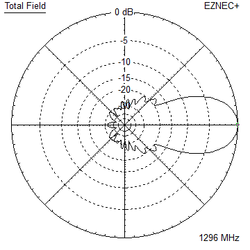
Gain vs. isotr. Rad.  14.0 dBi
Gain vs. Dipole       11.8 dBD
-3 dB E-plane         38.4 deg.
-3 dB H-plane         42.6 deg.
F/B                  -26.3 dB
F/R                  -23.1 dB
Impedance               50 ohms
VSWR Band Width       1.06:1 *
Mechan. Length        499.4 mm plus 2 x 15 mm offset
Electr. Length        2.15 λ

Stacking Dist. h-pol. (1296.2 MHz)
top-to-bottom         0.318 m or 1.04 ft
side-by-side          0.352 m or 1.15 ft

*) at 1300.0 MHz
How many VHF operators have been looking up this design since Dec. 2020?
Geometry
This Yagi with 3 mm elements through a 7.5 x 7.5 mm plastic boom
|
Ele. 3.0 mm DE 4.0 mm Boom 7.5 x 7.5 mm ABS Plastic Ele. fastening &. photo acc. F4FEY |
|

"Ready to saw and drill" data for mounting elements through this plastic boom:

The Drivers diameter is 4 mm.
The EZNEC model is done with Auto-Segmentation at 1296.2 MHz
This Yagi with 3.2 mm elements through a 7.5 x 7.5 mm plastic boom
|
Ele. 3.2 mm DE 4.0 mm Boom 7.5 x 7.5 mm ABS Plastic Ele. fastening &. photo acc. F4FEY |
|
"Ready to saw and drill" data for mounting elements through this plastic boom:
Imperial Boom 5/8"
|
This table is only valid for: Boom shape: square Boom dim: 5/8 x 5/8 inch Wall thickn.: 1.6 mm Holes in boom: 7.6 mm Offset rear: 300 mm Offset front: 40 mm |
|

Note: All the above include a "Segmentation Density Correction" (SBC) plus an offset for 23 cm of 4.52 mm per element
for compensation of the insulators as shown above in combination with SM5BSZ'S BC.exe values.
Note: with through Boom BC it is important to stick to the boom end offsets given below!
Read abt. the SBC here

The Drivers diameter is 4 mm for the plastic boom versions, 5 mm for the aluminium boom versions.
The EZNEC model is done with Auto-Segmentation at 1296.2 MHz
Pattern and VSWR Plots
Elevation and Azimuth plot at 1296.2 MHz


Return Loss and SWR plots - simulated

Downloads
None so far.
73, Hartmut, DG7YBN