-
• Main Page
- • Home
• Antennas - • 10.1 MHz
- • 14 MHz
- YBN 14-5wzsA compact class 28 ohms, 13 m boom 14 MHz 5 ele. straight split Dipole to be very uncritical for home building. A wideband version with hugh bandwidth and yet high F/B.
Elevation Plot
- YBN 14-5w rmcA full size 50 ohms, 15.4 m long 14 MHz 5 ele. with straight split Dipole to be very uncritical for home building. The Yagi covers the full 20 m band with a VSWR < 1:1.1
Elevation Plot
- YBN 14-5wzs
- • 18.1 MHz
- • 24.9 MHz
- YBN 12m-4wA 4.7 m long 24.9 MHz 4 ele. Yagi with straight split Dipole to be very uncritical for home building.
Elevation Plot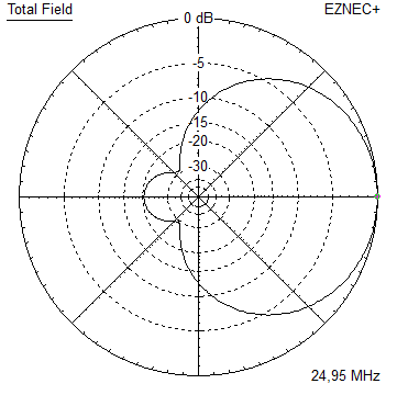
- YBN 12m-5nA 8.6 m long 24.9 MHz 5 ele. Yagi with straight split Dipole to be very uncritical for home building.
Elevation Plot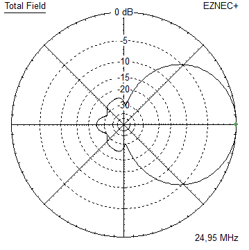
- GTV 12m-3mA 3.7 m long 24.9 MHz 3 ele. Yagi with with bent Dipole.
Elevation Plot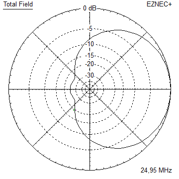
- YBN 12m-4w
- • 28 MHz
- • 50 MHz
- • 70 MHz


YBN 14-5w rmc 50 ohms Yagi with Conventional Driven Element
The YBN 14-5w full size boom length is a 50 ohms wideband beam covering the full 20 m band.
Design date of issue: 2020.10.24
Free space 3D pattern (14.3 MHz)

Performance Data
Specs: with tapered elements (30 > 25 > 20 > 16 mm) free space
		      14.2 MHz          14.3 MHz
Gain vs. isotr. Rad.  10.03 dBi		10.20 dBi
Gain vs. Dipole        7.88 dBD		 8.05 dBD
-3 dB E-plane         55.4 deg.
-3 dB H-plane         74.4 deg.
F/B                  -28.9 dB
F/R                  -19.2 dB
Impedance               50 ohms
VSWR Bandwidth        14.0 MHz = 1:1.06, 14.35 = 1:1.05
Mechan. Length        15.44 m exclusive boom offsets for elem. plates
Electr. Length        0.73 λ (14.2 MHz)

vert .Stacking Dist.
17.54 m or 57.5 ft
How many HF operators have been looking up this design since Oct. 2020?
Geometry
... is available in request
Pattern and VSWR Plots
Elevation and Azimuth plot at 14.3 MHz
RL and SWR plots - simulated

Tapered Model Azimuth plot 14.1 - 14.35 MHz
14.20 MHz F/B = 28.9 dB Gain = 10.03 dBi
14.30 MHz F/B = 28.6 dB Gain = 10.20 dBi
14.35 MHz F/B = 25.2 dB Gain = 10.28 dBi
Pattern and VSWR Plots over Ground
• At height of 16 m (perfect gnd assumed)
Azimuth plot at 14.1 MHz
• At height of 24 m (perfect gnd assumed)
Azimuth plot at 14.1 MHz
Validation of Tapering
Tapered Yagi:


73, Hartmut, DG7YBN