-
• Main Page
- • Home
• Antennas - • 10.1 MHz
- • 14 MHz
- • 18 MHz
- • 24.9 MHz
- • 28 MHz
- YBN 28-4wA 4.0 m long 28 MHz 4 ele. straight split Dipole to be very uncritical for home building.
Elevation Plot
- YBN 28-5wA 7.6 m long 28 MHz 5 ele. straight split Dipole to be very uncritical for home building. A wideband version with hugh bandwidth and yet high F/B.
Elevation Plot
- YBN 28-5LA 8.3 m long 28 MHz 5 ele. straight split Dipole to be very uncritical for home building.
Elevation Plot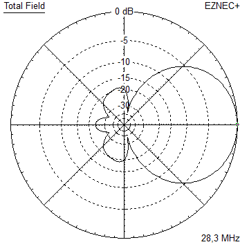
- YBN 28-6nA 9.6 m long 28 MHz 6 ele. straight split Dipole to be very uncritical for home building.
Elevation Plot
- YBN 28-7mA 13.9 m long 28 MHz 7 ele. straight split Dipole to be very uncritical for home building.
Elevation Plot
- YBN 28-7wA 13.6 m long 28 MHz 7 ele. straight split Dipole to be very uncritical for home building.
Elevation Plot
- YBN 28-8mA 17.2 m long 28 MHz 8 ele. straight split Dipole
Elevation Plot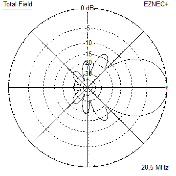
- GTV 28-4wA 5.2 m long 28 MHz 4 ele. with bent Dipole.
Elevation Plot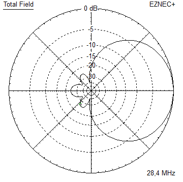
- GTV 28-7wA 13.7 m long 28 MHz 7 ele. with bent Dipole.
Elevation Plot
- GTV 28-9wA 20 m long 28 MHz 9 ele. with bent Dipole.
Elevation Plot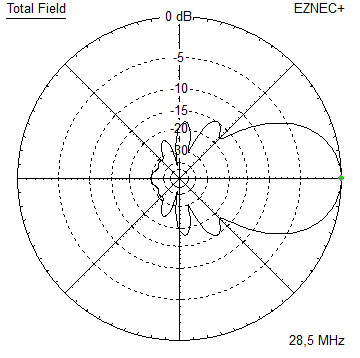
- GTV 28-9m LTA 23 m long 28 MHz 9 ele. with bent Dipole.
Elevation Plot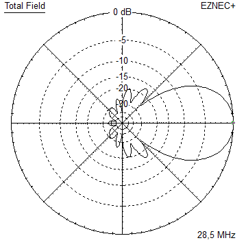
- YBN 28-4w
- • 50 MHz
- • 70 MHz
YBN 28-5w Yagi with straight split Dipole
CW + SSB band 28.0 to 28.5 MHz - 28 ohms version
On 28 MHz we should less look for gain but very clean directivity, because if the band is open successful DX more or less comes down to fade out unwanted signals. If we can easily produce a signal that enables us to ping our own echo when twice (!) around the globe with less than 100 watts of output, we may pass on 0.5 dB gain. And when band is closed that little bit would not help at all.
The patterns scattering factor (dt.: Streufaktor) as ratio of all rear and side lobes against the beam lobe is what we should look for in first place. Next we want forgiving behaviour according element length and tuning since shortwave Yagis are hard to post-tune on the pole and an exact taper factor.
Current distribution

Performance Data
Gain vs. isotr. Rad.  10.1 dBi
Gain vs. Dipole        8.0 dBD
-3 dB E-plane         55.2 deg.
-3 dB H-plane         74.4 deg.
F/B                  -28.8 dB
F/R                  -22.6 dB
Impedance               28 ohms
Mechan. Length        7626 mm
Electr. Length        0.72 λ

Stacking Dist. h-pol. (28.3 MHz)
top-to-bottom          8.76 m   or   28.7 ft
side-by-side          11.43 m   or   37.5 ft
Geometry
        Pos.   1/2 Length
                 in NEC

Refl.     0      2620
DE     1220      2575
D1     2070      2490
D2     4221      2390
D3     7626      2215
               ele. 20 mm

Driver an element diameter is 20 mm. No taper applied.
Use EZNEC's Auto-Segmentation at 28.2 MHz.
Drawing - to scale - except tube diameters and brackets

Building hints
Use L-profile brackets (see below), use U-bolts to clamp on boom and elements Given most short wave beams have to last very long on the mast I consider metal clamps and bracket compensation a good method.
Use Stauff-clamp OR thick walled plastic tube plus U-bolts for DE centre point.
Tapering Elements
Boom:     tube Ø 50 x 3 mm
Elements: tube Ø 20 x 2 mm on middle section
          tube Ø 16 x 2 mm on both sides

YO taper - lengths are per side

       Bracket   Ø 20     Ø 16       total span
Refl     135     1365     1186     2 x 2686 = 5372
DE       135     1265     1241     2 x 2642 = 5284
D1       135     1165     1255     2 x 2555 = 5110
D2       135     1165     1154     2 x 2454 = 4908
D3       135     1065     1077     2 x 2277 = 4554

Tube cutting table

      tube Ø 20      tube Ø 16
Refl    3000     1186 + 200 = 1386 (2 pcs.)
DE      2800     1241 + 200 = 1441 (2 pcs.)
D1      2600     1255 + 200 = 1455 (2 pcs.)
D2      2600     1154 + 200 = 1354 (2 pcs.)
D3      2400     1077 + 200 = 1277 (2 pcs.)

Element brackets L-profile 80 x 40 x 3 mm, l = 270 mm.
use U-bolts for 20 mm and 50 mm, the 50 mm ones with blocks.
(see DL4AAE, 4-Element-Yagi für 28 MHz, CQ-DL 12-2012
A note on tapering history
Read Joe Reisert, W1JR, Yagi/Uda Antenna Design, Part 1: A different approach, Communications Quarterly - Winter 1998
commenting on the Lawson, W6QHS methode
    "Tom Ring, WA2PHW, and Brian Breezley, K6STI, came up with an even better scaling and
    tapering solution. Remember that when you scale or taper an element, you are essentially
    trying to come up with an element that has the same electrical impedance at the new
    frequency. What Ring and Breezley did was to adjust the element lengths after scaling
    and tapering for the same electrical impedance using the YO (Yagi Optimiser) program."
Pattern and VSWR Plots
Elevation and Azimuth plot at 28.2 MHz
SWR and Return Loss plots - simulated with 4nec2 // Note the 100 dB scale
Downloads
EZNEC file of this Yagi
or simply the NEC input file
How to match to 50 ohms
1. Coax match
You may use the classic DK7ZB match. Go to http://www.mydarc.de/dk7zb/start1.htm and look for details.
Use a quality coax like the Ø 5 mm RG 302 B/U with PTFE dielectricum. (http://www.kabel-kusch.de)
2. Transformating quarterwave tube line
Copper tube (plumbers heating pipes)

inner tube Ø 10 mm, outer Ø 20 x 1 => Øi 18 mm results in Z = 35.3 ohms
inner tube Ø 15 mm, outer Ø 28 x 1 => Øi 26 mm results in Z = 33.0 ohms

Length is 2657 mm roughly
How to find precise numbers? => see on my Coax Line Imp. & Splitters Online Calculator page
Stacking
Note the good back lobe supression at that small distance. Mind this is short wave.
Signals may intrude from all angles.
Elevation plot and data of 5 over 5 array at 5.5 m stacking distances: free space / perfect gnd

                     free space    perfect gnd

Gain vs. isotr. Rad.  12.2 dBi       17.6 dBi
Gain vs. Dipole       10.0 dBD       15.4 dBD
-3 dB H-plane         55.8 deg.         -
-3 dB E-plane         44.8 deg.         -
F/B                  -22.8 dB           -
F/R                  -22.8 dB       -23.5 dB
Elevation plot and data of 5 over 5 array at 8.5 m stacking distances: free space / perfect gnd
                     free space    perfect gnd

Gain vs. isotr. Rad.  12.9 dBi       18.1 dBi
Gain vs. Dipole       10.8 dBD       15.9 dBD
-3 dB H-plane         55.8 deg.         -
-3 dB E-plane         33.4 deg.         -
F/B                  -27.8 dB           -
F/R                  -22.7 dB       -23.2 dB
73, Hartmut, DG7YBN