GTV 222-11w Yagi with bent Driven Element
Wideband OWA style medium size Yagi with focus on EME + SSB band but covering 222-226 MHz
This Yagi has very low back lobes for its length. It may serve as single antenna for portable
use and certainly make a useful 4 x vertical stack. It makes a quiet contest antenna due to its
high F/B. The bent DE (K6STI style) transforms from approx. 17 ohms to 50 ohms at feed point.
Current distribution
Performance Data
Specs: with 5/16 inch elements @ 222.1 MHz
Gain vs. isotr. Rad.  14.9 dBi
Gain vs. Dipole       12.8 dBD
-3 dB E-plane         34.5 deg.
-3 dB H-plane         37.6 deg.
F/B                  -31.4 dB
F/R                  -26.9 dB
Impedance               50 ohms
Mechan. Length        3858 mm incl. 2 x 30 mm stand off
Electr. Length        2.81 λ

Stacking dist. h-pol.
top-to-bottom         2.28 m or 7.47 ft
side-by-side          2.09 m or 6.87 ft
How many OMs have been looking up this design?
Pattern and VSWR Plots
Current distribution Elevation and Azimuth plot at 222.1 MHz
RL and SWR plot - simulated
Geometry
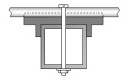
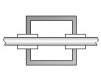
Sketch of bent dipole

Table 1: This Yagi with 5/16 inch elements on boom:
"Ready to saw and drill" data for mounting elements through boom with BC according SM5BSZ's BC.exe:
Note: with through Boom BC it is important to stick to the boom end offsets given below!
|
Ele. 5/16 in DE 1/2 in or 12.7 mm Boom 1 x 1 x 0.063 in |
Note: This includes a "Segmentation Density Correction" (SBC) of 3.14 mm
Read abt. the SBC here
Table 2: This Yagi with 4 mm elements through a 1 x 1 inch boom
|
Ele. 4.0 mm DE 1/2 in or 12.7 mm Boom 1 x 1 x 0.063 in |
"Ready to saw and drill" data for mounting elements through boom with BC according SM5BSZ's BC.exe:
Note: with through Boom BC it is important to stick to the boom end offsets given below!
|
This table is only valid for: Boom shape: square Boom dim: 1 x 1 inch Wall thickn.: 0.063 inch or 1.6 mm Holes in boom: 6.0 mm Offset rear: 30 mm Offset front: 30 mm |
|

This includes a "Segmentation Density Correction" (SBC) of 3.14 mm
for compensation of the insulators (7arrays.com
Note: with through Boom BC it is important to stick to the boom end offsets given below!
![]()
Downloads
None so far
73, Hartmut, DG7YBN