-
• Main Page
- • Home
• Antennas - • 10.1 MHz
- • 14 MHz
- • 18 MHz
- • 24.9 MHz
- • 28 MHz
- YBN 28-4wA 4.0 m long 28 MHz 4 ele. straight split Dipole to be very uncritical for home building.
Elevation Plot
- YBN 28-5wA 7.6 m long 28 MHz 5 ele. straight split Dipole to be very uncritical for home building. A wideband version with hugh bandwidth and yet high F/B.
Elevation Plot
- YBN 28-5LA 8.3 m long 28 MHz 5 ele. straight split Dipole to be very uncritical for home building.
Elevation Plot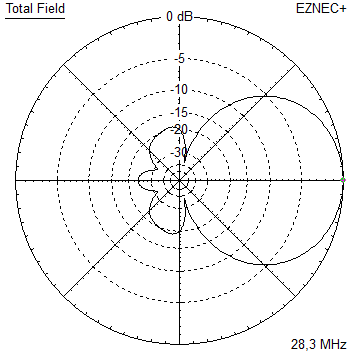
- YBN 28-6nA 9.6 m long 28 MHz 6 ele. straight split Dipole to be very uncritical for home building.
Elevation Plot
- YBN 28-7mA 13.9 m long 28 MHz 7 ele. straight split Dipole to be very uncritical for home building.
Elevation Plot
- YBN 28-7wA 13.6 m long 28 MHz 7 ele. straight split Dipole to be very uncritical for home building.
Elevation Plot
- YBN 28-8mA 17.2 m long 28 MHz 8 ele. straight split Dipole
Elevation Plot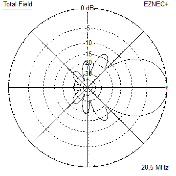
- GTV 28-4wA 5.2 m long 28 MHz 4 ele. with bent Dipole.
Elevation Plot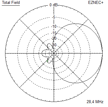
- GTV 28-7wA 13.7 m long 28 MHz 7 ele. with bent Dipole.
Elevation Plot
- GTV 28-9wA 20 m long 28 MHz 9 ele. with bent Dipole.
Elevation Plot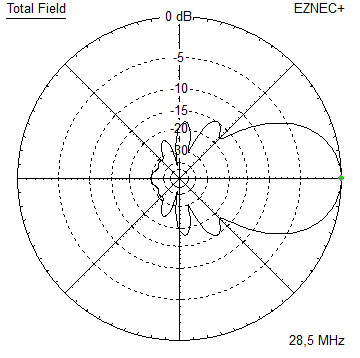
- GTV 28-9m LTA 23 m long 28 MHz 9 ele. with bent Dipole.
Elevation Plot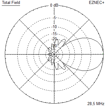
- YBN 28-4w
- • 50 MHz
- • 70 MHz
YBN 28-6n with straight split Dipole
Digi Modes + SSB band 28.2 to 28.6 MHz
On 28 MHz we should less look for gain but very clean directivity, because if the band is open successful DX more or less comes down to fade out unwanted signals. If we can easily produce a signal that enables us to ping our own echo when twice (!) around the globe with less than 100 watts of output, we may pass on 0.5 dB gain. And when band is closed that little bit would not help at all.
The patterns scattering factor (dt.: Streufaktor) as ratio of all rear and side lobes against the beam lobe is what we should look for in first place.
Design date of issue: 2020.08.20
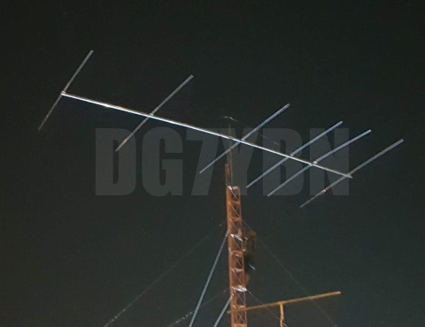
YBN 28-6n built by PY2ET, Roberto


YBN 27-6n = 27.5 MHz version built by PU2TDY. His qrz: 3at282

Dipole bracket (IZ1RFT):

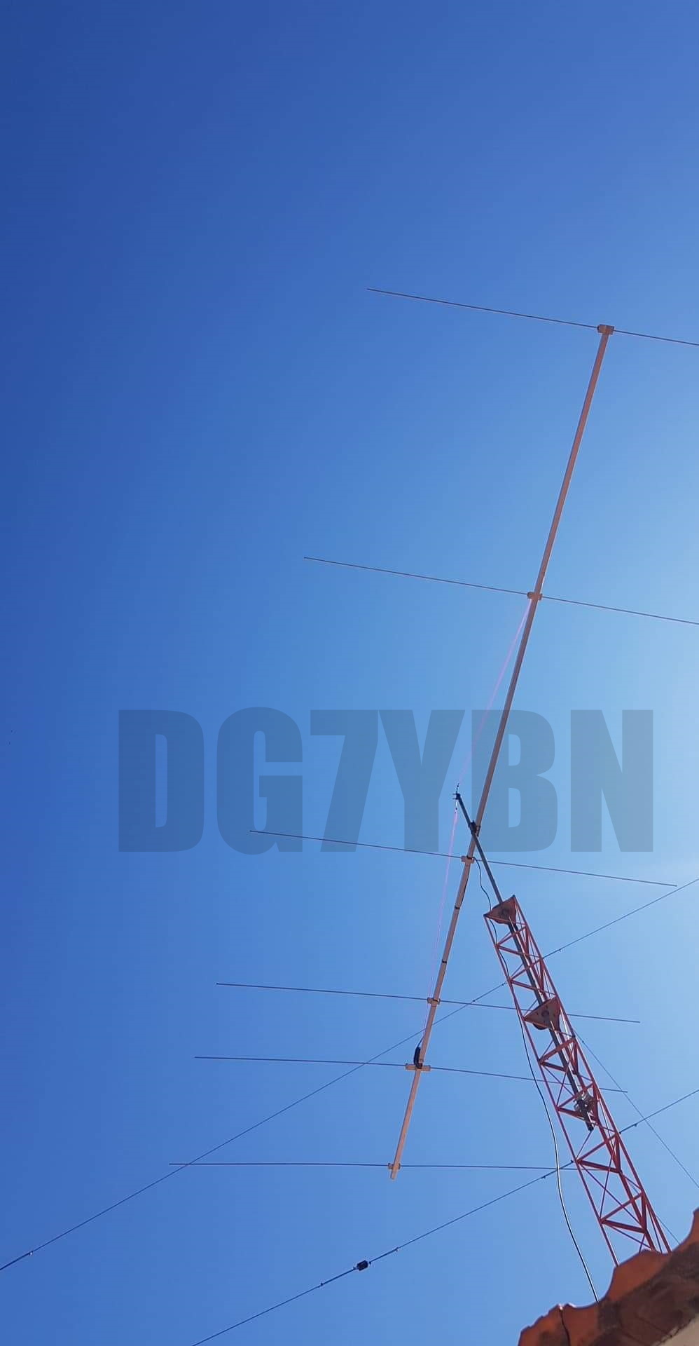
YBN 28-6n but by IZ1RFT


Size of bracket plates
Dipole: 230 x 42 x 20
Elements: 150 x 42 x 20
Matteo reports from pretest only 1 m above flat roof:
"Also today I have connected with 200 watt power of the icom 7700, stations from South America and do not believe that I have 1 meter antenna from the roof. I can't wait for it to be on the tower ..."
Current distribution

Performance Data (28.4 MHz, 16 mm el.)
Gain vs. isotr. Rad.  11.0 dBi
Gain vs. Dipole        8.9 dBD
-3 dB E-plane         50.4 deg.
-3 dB H-plane         63.0 deg.
F/B                  -21.2 dB
F/R                  -15.9 dB
Impedance               50 ohms
Mechan. Length        9598 mm
Electr. Length        0.91 λ

Stacking Dist. h-pol. (28.3 MHz)
top-to-bottom          10.1 m   or   33.1 ft
side-by-side           12.4 m   or   40.7 ft
Geometry
For building on a 40-50 mm boom, 16 mm elements insulated with hydraulic clamps like from co. Stauff:

Center of Gravity

How many pageviews did this design get since late Sept. 2020?
Pattern and VSWR Plots
Elevation and Azimuth plot at 28.4 MHz


SWR and Return Loss plots - simulated with 4nec2


27 MHz version YBN 27-6n
Geometry, 16 mm elements, centered to 27.45 MHz for building on a 40-50 mm boom,
16 mm elements insulated with hydraulic clamps like from co. Stauff:

27.6 MHz version for building on a 40-50 mm boom, 16 mm elements insulated with hydraulic clamps like from co. Stauff:

Pattern and VSWR Plots
Elevation and Azimuth plot at 28.2 MHz


SWR and Return Loss plots - simulated with 4nec2


Radiation pattern with Ground Gain
At 12 m above perfect ground

Gain vs. isotr. Rad.  16.65 dBi at  12 deg.
Gain vs. Dipole       14.50 dBD
F/B                  -20.6 dB   at 169 deg.
At 14 m above perfect ground
Gain vs. isotr. Rad.  16.71 dBi at   8 deg.
Gain vs. Dipole       14.56 dBD
F/B                  -22.7 dB   at 170 deg.
At 17 m above perfect ground
Gain vs. isotr. Rad.  16.88 dBi at   9 deg.
Gain vs. Dipole       14.73 dBD
F/B                  -20.6 dB   at 171 deg.
At 24 m above perfect ground

Gain vs. isotr. Rad.  16.91 dBi at   6 deg.
Gain vs. Dipole       14.76 dBD
F/B                  -21.6 dB   at 174 deg.
At 24 m above real ground:
For real ground in EZNEC we have to parametrize
soil condictivity in Siemens (S/m) and Dielectrical Constant.
Siemens (S) = 1 / Ω
It is clear that we seldom will have absolutely fitting values at hand
for the soil in mind to use for the simulation.
Nevertheless here is a simulation with whats predeclared in EZNEC
and a second on with half the conductivity for briefly assumed quite dry soil.
Desc.              predeclared    'Dry'
Cond.       (S/m)    0.005        0.002
Diel. Const  (/)        13           10
Real Ground : Predeclared Type

Gain vs. isotr. Rad.  16.67 dBi at   6 deg.
Gain vs. Dipole       14.52 dBD
F/B                  -21.5 dB   at 174 deg.
Real Ground : Dryer Type

Gain vs. isotr. Rad.  16.63 dBi at   6 deg.
Gain vs. Dipole       14.48 dBD
F/B                  -21.5 dB   at 174 deg.
Stacking

Elevation plot and data of 6 over 6 array at 10.1 m stacking distance

Gain vs. isotr. Rad.  13.97 dBi
Gain vs. Dipole       11.82 dBD
F/B                  -24.7 dB
Elevation plot and data of 6 over 6 array at 10.1 m stacking distance:
Lower Yagi 12 m, upper Yagi 22.1 m above perfect gnd

Gain vs. isotr. Rad.  18.9 dBi at   8 deg.
F/B                  -23.3 dB  at 172 deg.
Elevation plot and data of 6 over 6 array at 6 m stacking distance:
Lower Yagi 18 m, upper Yagi 24 m above perfect gnd

Gain vs. isotr. Rad.  18.8 dBi at   7 deg.
F/B                  -21.3 dB  at 173 deg.
73, Hartmut, DG7YBN