-
• Main Page
- • Home
• Antennas - • 40 MHz
- • 50 MHz
- YBN 50-2wA 1.2 m 50 MHz 2 ele. with split Dipole for direct 50 ohms feed to be very uncritical for home building. A wideband version with hugh bandwidth.
A project for an afternoon ...
Antenna View
- YBN 50-5wrc vsA 4 m 50 MHz 5 ele. with hairpin match and split Dipole to be very uncritical for home building.
Elevation Plot
- YBN 50-5wA 4.4 m 50 MHz 5 ele. derived from the 2 m 5 ele with split Dipole to be very uncritical for home building. A wideband version with hugh bandwidth and yet high F/B.
Elevation Plot
- YBN 50-7mzcA 7.96 m 50 MHz 7 ele. with hairpin match and split Dipole to be very uncritical for home building.
Elevation Plot
- YBN 50-9mA 13 m 50 MHz 9 ele. derived from the 2 m GTV 2-9m but with split Dipole to be very uncritical for home building.
Elevation Plot
- GTV 50-3wA 1.8 m 50 MHz 3 ele. Yagi. A wideband version with much bandwidth and yet relatively high F/B for its size
Elevation Plot
- GTV 50-6mA 6.8 m 50 MHz 6 ele. Yagi with very high F/B for its size
Elevation Plot
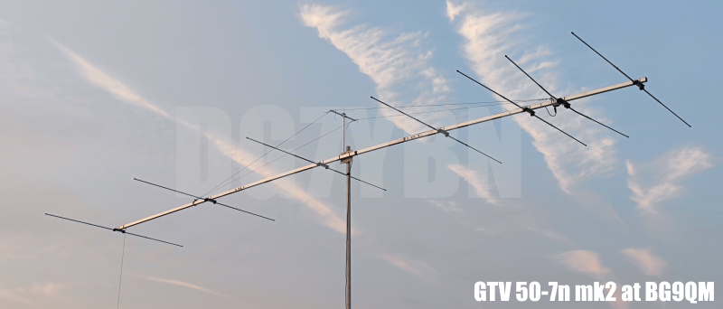
- GTV 50-7n mk2Revision of the very directive 8.6 m 50 MHz 7 ele. with bent Driver. Carefully tuned for some bandwidth and high F/R now - all without loosing on gain.
Elevation Plot
- GTV 50-8w10.7 m wide-band, still good G/T and nice F/B version of the low impedance, yet 50 ohms direct feed Low Noise Yagi with bent DE introduced in Dubus 1/2013
Elevation Plot
- GTV 50-10LT14.6 m very low noise, high G/T version of the low impedance, yet 50 ohms direct feed Low Noise Yagi with bent DE introduced in Dubus 1/2013
Elevation Plot
- YBN 50-2w
- • 70 MHz
- • 144 MHz
- • 432 MHz
GTV 50-7n mk2 with bent Driven Element
The old design? see here
EME + SSB narrow bandwidth version with improved F/B and F/R ( ... almost strictly G/T breeding *)
This medium length Yagi has a high F/R. It may serve as a contest stack or "small" but effective EME 4-Yagi-Bay.
The bent DE (K6STI style) transforms lower impedance to 50 ohms at feed point for direct feed. This Yagi is derived at on
the basis of the GTV2-8w with focus on F/R and relative bandwidth at above average class gain - a specific adaption to
the needs on the 50 MHz band were G/T is not all, see below.
(*) The G/T number is of limited use on 6 meters due to almost equal sky and earth temperatures; see here
So a few sidelobes will not spoil the performance of a 6 m design as much as it would on 144 or 432 MHz Yagis.
Nevertheless a clean pattern and some band width may always be welcome. The first one to keep as clear as possible
from side splatter or intense human made noise sources, the other for easy reproduction. The question is, how much
gain or wet weather stability is a designer willing to sacrifice to cleaner pattern or gaining some band width?
A good design for 6 m should be balanced between GAIN, F/R ratio and band width; emphasising these parameters
in order of appearance.
Performance Data
                    ele. 5/8 in.
Gain vs. isotr. Rad.  12.8 dBi (12.78 for those, who calculate with a sharp pencile)
Gain vs. Dipole       10.6 dBD
-3 dB E-plane         42.3 deg.
-3 dB H-plane         49.2 deg.
F/B                  -28.9 dB
F/R                  -23.1 dB
Impedance               50 ohms
Mechan. Length        8540 mm
Electr. Length        1.43 λ

Stacking Dist. h-pol.
top-to-bottom         7.18 m = 23.6 ft
side-by-side          8.28 m = 27.2 ft
GTV50-7n mk2 at BG9QM


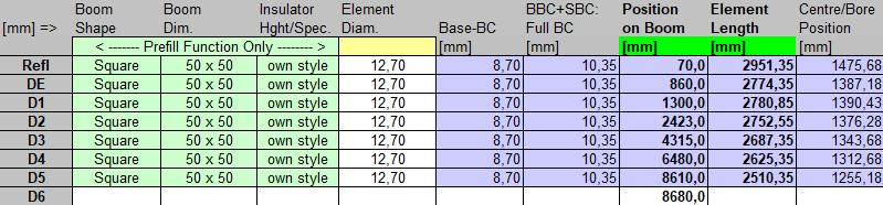
Geometry
Use EZNEC's Auto-Segmentation at 135 MHz.
"Ready to saw and drill" data for 1/2 inch (12.7 mm) elements on boom with BC acc. DG7YBN for Stauff Clamps:
|
Boom shape: square Boom: 50 x 50 mm inch Offset rear: 70 mm Offset front: 70 mm |
Stauff Clamps 2-12.7-PP |

Note: This includes a "Segmentation Density Correction" (SBC) of 1.65 mm
Pattern and VSWR Plots
Elevation and Azimuth plot at 144.1 MHz
RL and SWR plot - simulated ....(VSWR at 50.50 MHz is below 2.64 now)
Gain, F/B and F/R plot - simulated
Downloads
EZNEC file of this Yagi (5/8" and 16 mm ele.)
Stacking
Data of of 7 over 7 stack using DL6WU stacking distance 7.18 m = 23.6 ft
                     ele. 5/8" = 16 mm
Gain vs. isotr. Rad.  15.7 dBi
Gain vs. Dipole       13.6 dBD
-3 dB H-plane         42.6 deg.
-3 dB E-plane         22.0 deg.
F/B                  -32.1 dB
F/R                  -26.5 dB
Theoretical numbers, no phasing line lossesnor imperfections caused by H-frame included
Elevation and Azimuth plot and data of 4 Yagi bay using DL6WU stacking distances
Gain vs. isotr. Rad.  18.7 dBi
Gain vs. Dipole       16.6 dBD
-3 dB H-plane         18.9 deg.
-3 dB E-plane         22.0 deg.
F/B                  -33.5 dB
F/R                  -26.8 dB
Theoretical numbers, no phasing line losses
nor imperfections caused by H-frame included
Competition & Comparison
Comparing patterns with the G4CQM 6M7N50SY, which is an advanced design of equivalent length using a very tight
driver cell. Despite that Derek managing to stick to his preference of 50 ohms impedance at the feedpoint.
Derek and me had a little contest on designing a fine 1.4 wl 50 MHz Yagi. Both of us finally produced "mark 2"
versions of our base designs on which we settled in a "mutual agreement". For those who are interested I have
rolled out the full story "told in radiation patterns" per development step.
1. The new G4CQM vs. the original GTV
By publishing his 7 ele. N50SY design Derek had raised the bar higher ...
2. The G4CQM vs. GTV mk2
... and I responded to that with the GTV mk2 revision.
Gain and frequency sweep response show marginal differings only; the pattern does though. As emphasised above, a
distinctive first sidelobe will not be of much influence to a directive 50 MHz aerial.
 |
3. The G4CQM mk2 vs. GTV mk2:
... to which Derek responded with his N50SY mk2.
CQM 12.84 dBi (VSWR 2.84 at 50.50 MHz) - (in EZNEC) Numbers might vary slightly for Derek computes using K6STI's AO-Prof.
GTV 12,77 dBi (VSWR 2.62 at 50.50 MHz)
and finally the G4CQM mk3 (Attention: swapped colors, GTV in blue this time)
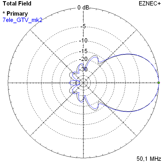
Which is better now? There is a difference of 0.07 dBi, traded in against more lobes and slightly less band width.
Gain is very much a figure of merit on 50 MHz - as probably a bit of security in achieving the simulated performance.
And what shall the Yagi be used for in what noisy environment?
Tnx Derrek!
To me the little design contest was welcome. It has pushed the performance of both our Yagis.
Both are quite usable designs but will need a steady hand when building due to the narrow band character.
Here is the link to G4CQM's website
73, Hartmut, DG7YBN