


Antenna Temperature Basics

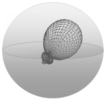
In Antenna Simulation Software we can adjust pattern computation step size in degrees. The little patch enlighted in the sky hemisphere (in sketch on left) is one of the resulting step size patches. The example shows just a single patch in straight main beam direction. Actually both hemispheres are clad with patches all over. Each of them shines onto the AUT's pattern with a brightness temperature. Depending on the hemisphere, the patch which belongs to this is either T-earth or T-sky. The AUT's radiation pattern holds the gain coresponding to each patch, starting with a normalised 0 dB in beam direction and likewise -24 dB for a side lobe. Now the pick up of noise power per patch is summed up, averaged over the full sphere and expressed in Kelvin. This is the AUT's antenna temperature.
What you see as a grid on the 3D radiation patterns surface (sketch on right) are just said patches on both hemispheres projected onto the radiation patterns volume.
At an elevation angle of zero degrees T-ant is (T-sky + T-earth)/2, for what ever Antenna we chose. No matter what radiation pattern, since every patch in the upper hemisphere has an equivalent patch in the lower hemisphere with exactly same gain into its direction. Despite that we may deduce a lot from the T-ant number taken at some elevation according the noise cancelling abilities or how quiet the AUT will be in terrestrial use. Since for a low T-ant we need low side and rear lobe levels, similar to what we need to listen to weak signals when noise sources from behind or side are about to overcast the tiny DX signal.

|
Misunderstanding Low Antenna Temperature - Fictitious Feedback on a Low Temperature Yagi Test
"During the March RCC fieldday we noticed that your new Low Temperature Yagi design is much quieter than the conventional Yagi we had set up as our reference. And further, to our own astonishment the Low Temperature Yagi was caught by white frost before the other in the early morning and also stayed covered in that for about 20 minutes longer too when the sun finally came out." |
Antenna Temperature is NOT about physical temperature of the antenna parts in degrees Celsius or Fahrenheit
Antenna Temperature is an equivalent to the noise power per band width that a hypothetical resistor at a noiseless receivers input would have to generate to produce same noise level as the antenna captures from the environment through its pattern characteristics (s. Nyquist Noise and Boltzmann Constant kb = 1.38 * 10E-23 J/K which links to temperature). Only the internal losses as far as due to ohmical losses inside the antenna wires or elements are subject to temperature sensitivity. But these, refering to increase of loss by increase of physical temperature by likewise 20 K or degrees Celsius are so marginal by numbers that even demanding applications can do without inclusing them. A much better way will be to chose good conductive material like thicker elements (see below).
A very comprehensive publication on the topic of understanding antenna temperature in its full physical context I came across on the internet is by Dr. Natalia K. Nikolova, McMaster University, Hamilton, Canada. It is a lecture from her 2012 course "Modern Antennas in Wireless Telecommunications" http://www.ece.mcmaster.ca/faculty/nikolova/antenna_dload/current_lectures/L07_Noise.pdf
Antenna Temperature and G/T System
G/T_System is a measure proportional to Signal/Noise ratio at the speakers of our radio with ΔG/T = ΔSNR[1,2].
The Antenna is first member in the RX chain. Followed by losses in the coax to the coax relay and so on until down to the Receivers NF. The Low Noise Amplifier not only amplifies the signal and noise from the antenna, it also adds its effective input noise temperature to the Noise Temperature the antenna delivers.

Hoefsloot, P., PA3BIY, A Very High Dynamic Range LNA for 144 MHz, Dubus 1/2002 A pre-amplifier will never improve the signal-to-noise (SNR) ratio! The SNR at the antenna plug is the best we are ever able to obtain. Any noise added by the amplifier will deteriorate the SNR, so we want to minimise that amount of noise. The ambient noise [ ] sets the limit to the SNR and can be expressed as dB above the thermal noise T0 (T0 = 290 K).
... if we use that statement out of context to the package [antenna noise pick up and mast bound preamps NF] it might not be satisfying. A preamplifier does not improve the S/N in all components between antenna and its placement in front of the transceiver. As its NF adds to the noise floor. That we need to amplify the whole spectrum that shall be processed in the noisy mixers and following stages until down to audio in our transceiver in order to attenuate the inevitable degradation of the S/N in these stages is understood.
So that a good preamp compensates for what we loose in the following stages as best as it can and in doing so helps to retain the most of what is provided at the antenna terminals ... but for sure adds its own noise to the noise floor of the just picked up signal-to-noise. The interaction of first preamp and the limits according best S/N set by the antennas temperature is what PA3BIY reminds us. No more, no less.
1. The conclusion, that G/T is proportional to SNR: UR5EAZ: MS Exel "NF_GT_DELTA_SNR_V1.xls, Effective Noise emperature & G/T Calculator,
Moon Net, Message #38631, 2021-09-21; Quote ’ΔS/N = ΔG/T’
2. UR5EAZ: Program RFNC, V 1.1, 2025-12-06; dg7ybn.de/Ant_soft/Ant_Software.htm#RFNC
Quote ’the signal to noise ratio SNR (S/N) is proportional to M (G/T)’
What do "Low Noise" and "Low Temperature Yagi" stand for?
1. Brightness Temperature: Everything emits radio waves in relation to its temperature; all bodies, stars, constellations, earth ground ... . Most emissions are of very broad band nature and unspecific orientation / polarisation. To quantify emission intensity of such we use the term "Brightness Temperature". The higher the radiation temperature the "brighter it emits".
And then man made noise and QRN add their share to this, see below -> Real life RX situation.
2. Our RX Frontend will see what the Antenna picks up: Any PreAmp and mixer stage will add its own noise. So it is up to the directive antenna to source out signal from direction x and noise from all other directions. The antenna will manage that task the better, the higher the gain is. But gain describes just the main beam lobe and the wanted signals amplification hence. Noise, in its magnitude described as Noise Temperature comes from all around. There is noise from the Milky Way, noise from the sun, from certain star constellations, from defective or moist high voltage line insulators, our neighbours Plasma TV or washing maschine or birdies on frequency emerging from CATV networks or the close by amateur calling CQ just 4 kHz below of where you try to read a weak DX station.
The directive antenna will do better when of high directivity factor (dt.: Richtfaktor). Which means high gain mostly in signals direction only. Less sidelobes result in higher directivity factor.
3. Real life RX situation: Now even in the simplified classic Antenna Temperature thru Tsky and Tearth model we have a noise level of 250 K "shining down" from the sky hemisphere plus 1000 K affecting our reception from hot earth on 144 MHz. These are averaged numbers in order to have a uniform and standardised artificial test environment for computing comparable Antenna Temperatures.
In real life situations Tearth often exceeds 1000 K = 6.5 dB easily. Often it is far from being spread uniformly on the full 360 degrees of sight too. I notice peaks up to 3200 K = 10.8 dB at my city QTH reading a full 360 degree sweeps noise level for instance. In a contest situation we all suffer from some dB's of splatter from time to time. If that is 2 S-meter readings or 12 dB then 4306 K will be added to the Noise for the S/N equation. But these come in from narrow angles on the azimuth pattern.
Recap: The so called "Low Noise" or "Low Temperature" Yagis aims to perform with best directivity factor and low internally generated noise. That means cancelling all but the main beams direction best as possible and acheive lowest noise floor. Which will block the unwanted S2 splatter from side or backward direction by much more that a conventional Yagi. If we can cancel 10 dB on that irritating signals direction we will save 2600 K of noise that would otherwise have degraded our S/N on the wanted DX signal. The Low Noise Yagi potentially picks up less noise; it delivers less noise temperature to the antenna terminals and thus may be called a "Low Temperature" antenna. Which it is in relation to a standard Yagi.
"Internal Noise" as Thermal Noise Temperature caused by Element Losses
1. Passive Components: For passive components an increase in physical temperature leads to an increase in Noise Temperature. To a 50 ohms system a 50 ohms resistor will introduce 290.0 K at 16.85 degrees Celsius; respectively 300.0 K at 26.85 degrees Celsius.
2. Nyquist Noise Power: Connecting said resistor to the RX-input we can "hear" it producing noise. The more, the hotter it gets. This is not due to emitted radio waves but to Nyquist Noise. Noise Power is P = kB * T * B; kB = Boltzmann's Constant, T = Temp. of device in Kelvin, B = RX's Bandwidth.
However, the emitted radio waves spectrum is mostly very broad, so that the Nyquist formula is reduced to "Spectral Power" = kB * T. Related to antenna temperature this noise stands for Noise Power generated in the antennas internal structure. The full amount of Antenna Losses is caused by the interaction of losses in antenna elements or wires and current profile on those elements. It does not work out to just look after the ohmic losses in the cross section of planned to use aliminium, copper, steel etc. according the materials conductance. The generated Noise Power depends on how many meters of that cross section are used in the quoted design and what amount of current runs through these elements altogether.
EZNEC and 4nec2 provide all these numbers enclosed in the Far Field Table (FFTab). TANT and AGTC read them from the FFTab file and produce the values for T_pattern, T_loss and T_total at given Brightness Temperatures of sky and ground.
Typical numbers for T_loss at VHF/UHF are 3 ... 12 K for aluminium elements, but increasing to approx. 30 K for thin stain less steel elements. Again: the design itself has a large influence on the internal noise - a DL6WU design, very carefully trimmed in order to place every next element exactly in right phase of the travelling wave leads to half the internal loss that most other designs will - at same materials used.
3. How large is the impact of internal noise on the overall noise or temperature a Yagi will provide? Taking an average Bay of 4 x 10 elem. on 144 MHz we find a ratio of 250 K picked up from emitting sources from outside thru the pattern characteristics vs. 8 K internal noise. On 432 MHz we find a different setting. Due to the much lower average "outside" noise level we find some 30 K external noise pick up against some 5 ... 8 K internal noise on a bay of 4 x 17 elem. Yagis. Frankly - on 50 MHz internal element losses are of marginal importance only, on 144 MHz be careful, on 432 MHz they are a serious figure.
Also see at SM5BSZ:
Losses in yagi antenna elements at 144 MHz, sm5bsz.com/antennas/sa/losses144.htm
Losses in yagi antenna elements at 413 MHz, sm5bsz.com/antennas/sa/losses413.htm
4. T_total: Noise pick up from the environment and internally generated noise are summed up to total Antenna Temperature.
TANT and elder version of AGTC produce numbers for T_pattern, T_loss and sum to T_total:

Relevant literature often uses the Loss Factor La instead of the Average Gain.
5. How much does the Internal Thermal Noise Temperature add to the overall Antenna Noise Temperature?
Example Calculations using the formula given above
Keep in mind that this noise is but man made by design and construction materials. Any lossy materials added to elements will increase that noise, like pushed on starlock washers, end caps made from lossy plastics, very broad insulators from cheap materials, thick coatings with bad conductivity, thick oxide layers grown as the antenna ages ... mind the skin effect.
The shown losses will add to our overall RX systems noise figure like the performance number of noise figure of the LNA will. We spend much on decreasing Preamp noise figure from say 0.50 to 0.38 dB. But what about the noise level we get in from the antenna terminals then?
AGTC-JS_V01-08
HTML with Javascript-based Antenna Temperature and G/T calculation program
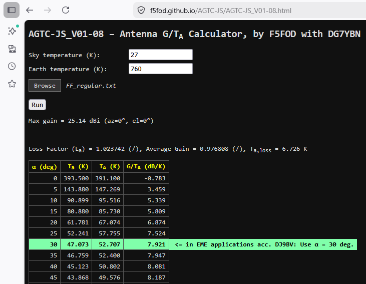
The functionality of the QBasic compiled DOS progam AGTC in a single HTML-file web utility.
Link: https://f5fod.github.io/AGTC-JS/ on github
• Safety Informations:
This is free software.
Liability is therefore excluded to the greatest extent possible. See also
Directive (EU) 2024/2853 Liability for defective products.
AGTC_lite - a DOS Antenna Temperature and G/T calculation program
AGTC_lite was progammed by F5FOD with help from DG7YBN.
This program reads antenna gain per angle sector from a specified .txt file and processes these data.
It runs on 32 and 64 bit machines. You can use it with win7 without running it in DOSBOX or similar emulator.
Read en detail about the AGTC and background ...
here ...
Both EZNEC 5+ and 4nec2 (v.5.8.9 on)* offer to export such a Far Field Table (FFTab).
(*) see "4nec2 goes TANT", Dubus 3/2012
• Current Version 1.58 of AGTC_anyGTa_2lite (Nov. 2019)

• AGTC_lite startup screenshot
AGTC_lite computing

AGTC_lite screenshot - computation accomplished

The AGTC_lite DOS Console program is developed in Basic. The .exe file is compiled with the QB64 compiler. AGTC_lite holds improved test for length of FFtab files and displays the name of the engaged with FFTab file in its window frame header. Which is welcome for documentation in form of screenshots.
AGTC_lite does not only compute Antenna Temperature and G/T. In its headline you find the Average Gain of the model examined, both in numeric and dB numbers and determind forward gain. Further internal Antenna losses expressed as Loss Temperature. Unlike TANT the AGTC_lite converts the decimal separator used in the FFtab file.
The output lines show numbers from zero to 90 degree elevation with the 30 degree line highlighted in red. That is the number commonly used to compare different antennas abilities. It represents a typical evevation for EME. Actually this angle is nothing but a convention. But we need one, don't we?
Example of FFTab file
The angle notation convention must be turning CCW (counter clock wise) in EZNEC and 4nec2, gain must be expressed in dBi, pattern angles theta and Phi must be set the right way. Finally angle resolution must be 3 degrees at least. Model must not necessarily be set up in a way that maximum gain occures at 0 degrees (x-axis). AGTC_lite will compute with maximum gain occuring at any angle.
Read more on how to derive a NEC model for AGTC_lite or TANT in the official TANT Manual
AGTC_lite Characteristics Summary
− Mathematical method completely described and demonstrated in Dubus 1-3/2017
− Open source Basic code, very readable and fully documented (QB64)
− May be rewritten in any modern language and interface
− Any asymmetrical pattern allowed, with maximum gain occurring at any angle θ, φ
− Trapezoidal calculations for surface integration = exact, no rotation calculations nor interpolations of any kind
− Hence: high accuracy whatever the antenna tilt angle, including 90 degrees
− Automatic conversion of decimal separator from comma to dot in FFTabs
− Very long FF Table file names allowed (no restriction to 5+8 DOS file names)
− Flexible choices of antenna tilt angle computation range
− Enhanved TANT format output screen
− Including FF Table file name, Sky and Earth Temperatures, average gain, max gain azimuth & elevation
− Enables to secure all the essential documentary information in one screen capture
− Option: formatted printout file holding the data needed, including the values of zones
− Extensive error handler texting feedback to help you in case of difficulties
TANT - a DOS Antenna Temperature and G/T calculation program
TANT was progammed by YT1NT, on proposal of YU7EF and with help from YU1CF + YT1NP.
This program reads antenna gain per angle sector from a specified .txt file and processes these data.
Both EZNEC 5+ and 4nec2 (v.5.8.9 on)* offer to export such a Far Field Table (FF Tab).
(*) see "4nec2 goes TANT", Dubus 3/2012
TANT startup screenshot

TANT screenshot - computation accomplished

TANT does not only compute Antenna Temperature and G/T. In its headline you find the Average Gain of the model examined and determind gain in direction of zero degrees on x-axis, both in numeric and dB numbers. Further internal Antenna losses expressed as Loss Temperature. The output lines show numbers from zero to 90 degree elevation with the 30 degree line highlighted in red. That is the number commonly used to compare different antennas abilities. It represents a typical evevation for EME. Actually this angle is nothing but a convention. But we need one, don't we?
Example of FF Tab file
Note the rows per angle and per elevation angle slice. To have the table compliant for TANT the comma must be used as decimal separator. The angle convention must be turning CCW (counter clock wise), gain must be expressed in dBi, pattern angles theta and Phi must be set the right way. Finally angle resolution must be 3 degrees at least. Model must be set up in a way that maximum gain occures at 0 degrees (x-axis).
Read more on how to derive a NEC model for TANT in the official TANT Manual
System Temperature and G/T Calculation Table Sheet - by UR5EAZ
To download this MS Excel click here:
On courtesy of Vladimir, UR5EAZ
What Temperatures to use as T_sky and T_earth on which Band?
Rev. 2020-05-31 with 2/2019 data
For full data and explanations see Dubus Article:
Update to Sky and Earth Temperatures for VHF/UHF Amateur Radio Bands
An abstract of development of modern radio astronomy and terrestrial radio noise measurments, leading to a proposal for an up to date set of sky and earth radiation temperatures for simulations in the VHF/UHF range. Dubus 2/2019
An abstract of development of modern radio astronomy and terrestrial radio noise measurments, leading to a proposal for an up to date set of sky and earth radiation temperatures for simulations in the VHF/UHF range. Dubus 2/2019
• Man-Made Noise consolidated

Chart 1: ITU-R 372-13, [1], (left side lines) and University Gent / OFCOM measured data dated 2010, [2], (on right).
The OFCOM measured data open a bit of contrast to the published in 2016 data in the latest ITU Recommendation. Which are
based on constants published in 1994.
Source of Fig.: Dubus 2/2019 pg. 116, Chart 5, [3]
Source of Fig.: Dubus 2/2019 pg. 116, Chart 5, [3]
• Y-Factors
Table 1: Y-Factor from Tsky per Reich & Reich [4] values and Tearth for 50 - 144 MHz from
latest ITU Recommendation [1] and 222 - 432 MHz from Radio Science Bulletins Man-Made Noise in Our Living Environments [2].
Source of Table: Dubus 2/2019 pg. 117, Table 11, [3]
Source of Table: Dubus 2/2019 pg. 117, Table 11, [3]
• Temperatures used in the VE7BQH Antenna Tables
Table 2: Temperatures used in the VE7BQH Antenna Tables,
+) Calculated and rounded from noise figure (dB) per formula given in ITU-R [1]
(**) Tsky for 50.15 MHz is produced from the ITU recommendations P.372-13 [1]
*) read and rounded from Gent University / OFCOM [2]
Source of Table: Dubus 2/2019 pg. 116, Table 9, [3]
+) Calculated and rounded from noise figure (dB) per formula given in ITU-R [1]
(**) Tsky for 50.15 MHz is produced from the ITU recommendations P.372-13 [1]
*) read and rounded from Gent University / OFCOM [2]
Source of Table: Dubus 2/2019 pg. 116, Table 9, [3]
[1] International Telecommunication Union, ITU-R P.372-13, Radio Noise, Geneva, 10.2016, https://www.itu.int/rec/R-REC-P.372
[2] Lefering, F. et al: Man-Made Noise in Our Living Environments, Ghent University (INTEC), Radio Science Bulletins No. 334, 09.2010
[3] Klüver, H., DG7YBN: Update to Sky and Earth Temperatures for VHF/UHF Amateur Radio Bands, Dubus 2/2019
[4] Reich, P., Reich, W.: A map of spectral indices of the Galactic radio continuum emission between 408 and 1420 MHz for the entire northern sky, Astronomy & Astrophysics
It is understood, that the above represents a set of mean temperatures as standardised numbers that alow us to compare antenna designs according their antenna temperature and G/T_ant. The actual T_earth at your QTH might be quite different though care has been taken to adjust these mean numbers. If you would like to do an explicite real world calculation valid for your location you will have to measure ground noise temperature yourself and replace numbers.
Regarding mean numbers same applies to sky temperature. Beaming at a star constellation, milkyway or sun will result in a quite differing number. The shown sky temperatures are an average over the whole hemisphere as this is the only way to produce numbers, that enable us to directly compare two antenna arrays in antenna temperature and G/T_ant, which is equivalent to S/N at the antenna terminals.
Y-Factor Antenna Temperature wise
Rev. 2020-05-31 with 2/2019 data
This is not about measuring a Y-Factor of an actual antenna or RX system with the known "hot / cold" method, but meant to give an overview on how much the general ratio T_earth / T_sky can give a guideline on what parameters to emphasis when designing Antennas for what band.
As a simplified model, which may serve to judge the importance of antenna temperature on a specific band we may use an isotropic radiator and the ratio of T_earth / T_sky on that frequency. The isotropic radiation pattern will see similar amounts of brightness temperatures from lower hemisphere = T_earth and upper hemisphere = T_sky.
The only thing be done is to calculate the ratio Y = T_hot / T_cold = T_earth / T_sky.
Examples for the omnidirectional antenna (residentail area Tearth)

Y( 50 MHz) = 100600 K / 5640 K =  17.8
Y(144 MHz) =   5400 K /  290 K =  18.6
Y(432 MHz) =   1800 K /   27 K =  66.7

Chart 1: Tearth, Tsky and Y-Factor from Tsky per Reich & Reich values as in [2, s. above] and Tearth for 50-144 MHz from ITU-R [1, above]
and 22-432 MHz from [2, above].
Source of Fig.: Dubus 2/2019 pg. 117, Chart 6, [3, s. chapter above]
Source of Fig.: Dubus 2/2019 pg. 117, Chart 6, [3, s. chapter above]
From this we can deduce the importance or impact the antenna temperature number will have on what band - or in other words ... how much care should be taken on what band to design yielding low Antenna Temparature and nice F/B, or highest gain.
Conclusions (on the omnidirectional antenna):
• For 50 MHz the Y-Factor was so far assumed to be close to 1. With the newer findings it turns out it can be around 18 an much higher in city or close to industrial environments. Which cetrainly does give Antenna G/T a meaning for this band.
• On 144 MHz the T_ant is and was meaningfull, a Y-Factor around 18 in residential areas alone does make strong case .
• On 432 MHz the more, since the crude construct of Y-Factor for the isotropic radiator is 66 or coarsely 4 x the number we have on 144 MHz.
Because of the much larger Y-Factor on 432 MHz the antenna temperature has a much greater impact on the Signal/Noise Ratio at the antenna terminals than on 144 MHz.
To download AGTC_lite as a .zip file, go to the AGTC website here
Safety Informations:
This is free software.
Liability is therefore excluded to the greatest extent possible.
See also Directive (EU) 2024/2853 Liability for defective products
Download TANT as a .zip file, here
Safety Informations:
This is free software.
Liability is therefore excluded to the greatest extent possible.
See also Directive (EU) 2024/2853 Liability for defective products
TANT on 64 bit Operating Systems (win7 and up) ?
64 Bit OS like win7 offer a number of 'compatibility modes' to get DOS applications running in the DOS console. None of them works smart enough to bring up TANT or similar DOS software. To run TANT on a 64 bit Operating System you will need to either install a Virtual Machine that executes winXP (like VM Ware) and run from there or use the DOSBOX x86 emulator or for details see (http://www.dosbox.com/wiki/Main_Page).
How to run TANT in DOSBOX Emulator
Install DOSBOX (www.dosbox.com). DOSBOX is free and an Open Source project. Mount the folder containing TANT like a drive in UNIX and run it from there.
Below you find a brief description how to start TANT in DOSBOX - tnx IZ2FLY!
DOSBOX prompt: ... use some long forgotten DOS command lines ... , hi

Lets imagine a folder named "my_TANT" which holds the TANT.exe.
It is placed right on drive c:

When starting up DOSBOX it will appear as an extra Drive, let it be 'Z' in our example

(.) prompt is      Z:\ > _
(1) type           mount c c:\my_TANT                                   & return
(.) prompt shows   Drive C is mounted as local directory c:\my_TANT
(.)                Z:\ > _
(2) type           C:\                                                  & return
(.) prompt shows   C:\ > _
(3) add            TANT.exe                                             & return

... this should start TANT. Now proceed as usually.
What I found a bit peculiar is that you mount the folder 'my_TANT' as drive c: here.
Thus changing to c: in DOSBOX opens folder 'my_TANT'.

Some old DOS commands that might help
(1) 'x:\'  & return => change to directory or drive x:
(1) 'cd..' & return => to step down one directory
(2) 'dir'  & return => to list content of current directory
You can even configure the DOSBOX autoexec.bat by a right side mouse click on its desktop icon. A DOSBOX properties window will open, in which you may lay down command lines the DOSBOX shall execute at startup. Basically these may be same as in example above. Thus TANT will start automatically after DOSBOX is started.
Please note: DOSBOX is Freeware. Though I explain how to use TANT in DOSBOX no guarantee is given, whatsoever, use DOSBOX at your own risk
Note: The logos, notations, brands and trade names shown or mentioned on this website are the property of the correlating companies and are subject to trademark rights !
73, Hartmut, DG7YBN