 
 
Antenna design development unfolding ... |

|
Since the invention of the Yagi-Uda antenna it has been a long way to make it the actual low noise, high gain antenna that works so well in weak signal communications.
Milestones in developing the Yagi-Uda design
Below I have listed a number of what I think are outstanding milestones in Yagi antenna development. This is a subjective listing. It is not meant to cause any offence to unlisted designers achievements. Like I think that K1FO's "An Optimum Design for 432 MHz Yagis", QST 87/88 might be placed somewhere between the DL6WU Double Optimised Approach and the DJ9BV Opt.-series. But I do not have enough facts about who was first at what here. Where I reflect on early inventions or for example using low impedance to produce maximum gain on Yagis and feeding them with a folded dipole these are facts with indicated sources. This does not mean that there might not have been such designs even earlier.• 1924 - Anyway the plot started in 1924 with Assistant Prof. Shintaro Uda and Prof. Hidetsugu Yagi at the Tohoku Imperial University, Sendai, Japan. First publication in Japanese - English translation "Projector of the Sharpest Beam of Electric Waves"
With the first publication in English by Yagi in 1928 in the US: "Yagi, H.: Beam Transmission of Ultra Short Waves. In: Proceedings of the IRE. 16, Nr. 6, Juni 1928"
tearing down the language barrier and Prof. Yagi applying for patents a Japanese invention made it around the world. Even though Yagi referred to the credits of Uda the antenna became known as "Yagi" but should be named Yagi-Uda.
Sources: http://en.wikipedia.org/wiki/Shintaro_Uda and https://www.jstage.jst.go.jp
• 1956 ... 1972 - During that phase several publications on high gain Yagis were made by Carl Greenblum & Edward Tilton - W1DHQ, Dr. Hermann Ehrenspeck, Don Hilliard, W0EYE (now W0PW) and others -
you may find a good read at http://www.wb4hfn.com/Resources/ANTHY4.TXT
• Shintaro Uda & Yasuto Mushiaka, "Yagi-Uda Antenna", The Research Institute of Electronical Communictaions, Sendai, Japan, 1954
• Carl Greenblum, "Notes on the Development of Yagi Arrays - Part I & II, QST Aug. & Sept. 1056
• Edward Tilton, W1HDQ, "Yagi Arrays for 432 MHz", QST Apr. 1966
• D. Cheng, C. Chen, "Optimum element spacings for Yagi-Uda arrays", IEEE Transactions on Antennas and Propagation, vol. 21, no. 5, 1973
• James Lawson, W2PV, "Yagi Antenna Design: Performance Calculations" ham radio, Jan. 1980
• 1976 - In my oppinion nothing beats Peter P. Viezbickes 'NBS Technical Note #688'
Link in higher quality scan on google books

Pic. on left: Source - Cover of said paper: US National Buero of Standards and Technology
Pic. on right: Current Profile of 15 ele. NBS Yagi
The NBS note 688 holds a lot of basic facts on element lengths, spacings, scaling, patterns and stacking; BTW: similar stacking charts and gain numbers as by DL6WU. If you think that low impedance Yagis as such, or feeding them by taking advantage of a folded dipoles tranformation ratio are an achievement of modern times designers - they are not. Model one of the described NBS Yagis in NEC using a simple straight split dipole and find an impedance below 25 ohms.
     NBS Note 688, pg. 17: 'For a 50 Ohm Impedance, a folded dipole
                       and a quarter-wave balun can be employed.'
Not surprising,
since the sense of that paper was to seek for gain per boomlength. We see a large spacing between Dipole and 1st director element,
as typical for 12.5 ohm DK7ZB designs. And a nearly to be called a 'current optimised' design. Only the rear lobes are not quite as they
could be. But this is dated 1976, zero computer opimisation added. Pure handwork.
• 1978 - DL6WU's approach of double opimised Yagis by means of element lenghts and spacings, his stacking formula and more; pure handwork too.
- - - - - Enter NEC - - - - -
• 198? - Tom Kirby, W1EJ's computer optimised Yagi-Uda antennas. He cound make use of computer software developed at Ohio State University.
• 1987 - K1FO's "An Optimum Design for 432 MHz Yagis", QST 87/88 - part 1
• 1987 - DJ9BV introducing Antenna G/T as a figure of merit to the amateur radio community in his Dubus article 'Effective Noise Temperature of 4-Yagi Arrays for 432 MHz EME'
• 1990/91 - DJ9BV's computer aided optimisation on DL6WU designs:
(1) The BV-series for 144 MHz (1990)
(2) The OPT-series 'dropping the DL6WU constraint of 50 ohms feed impedance' to 33 ohms (1987 - 1991);
the also low impedant K1FO's 'An Optimum Design for 432 MHz Yagis' in QST 12/1987. Anyway the two worked closely together (see above).
Both DJ9BV series still being scalable in length series in DL6WU tradidtion. The 432 Mhz OPT still ranking strong in the 432 MHz G/T Table today.
• 1995 - DK7ZB promoting low impedance Yagis with straight split DE in combination with parallel coax transformer ('DK7ZB-match')
In doing so, he pioneered 28 ohm Yagis as easy to feed low impedance Yagis without need to produce a T-match or similar (1995-1998)
With this he poineered producing Yagis with a Feedpoint impedance of 28 ohms with a match the can be arranged easily, by means of not having to create a T-match or similar (1995-1998). In the sum of parameters gain, back lobe suppression and usable band width a feedpoint impedance around 10 .. 35 ohms normally yields better properies compared to a 50 ohms feedpoint impedance. In all cases where this is not achieved inside the Yagi-Uda by opting for an appropriate radiator (see LFA Loop, Folded Dipole 12.5 to 50 ohms and V shaped bent dipole as K6STI's initial produce). This was all known before DK7ZB's approach. We likewise find DJ9BV settling on approx. 33 ohms as impedance for his OPT series around 5 years earlier then the first publications of DK7ZB, s. above. However the arranged in paralled twinned 75 ohms quarterwave line to match 28 ohms is a smart approach due to the availibility of the 75 ohm coax. Which he repeated a few years later by introducing the 2 x 50 ohms to 12.5 ohms at feedpoint transformation line.
• 1996 - VE7BQH's Article 'G/T for Yagis' in Dubus 1/1996
An essential data source to determine progress of designs by numbers such as Antenna-G/T, Antenna temperature and Gain per wavelength of boom tube.
• 1998 - DJ9BV (3) The BVO series, a design that has lost the scalability in favour to unique properties for a native 50 ohms design and the time being
• 2006 - YU7EF's 'Low Temperature Antennas' approach to Yagi design objectives
A primer in low noise Yagi design, YU7EF set standards on pattern cleanness which still are a reference to all influenced designers of high G/T through low temperatur Yagis in 2012. Most of his designs show a characteristic current distribution along the boom with a break in around the very first directing parasitc elements. This feature was to become a fingerprint found on most of the successful Yagis made by Designers that are following his idea.
• From 2010 - G0KSC's approach of very tight spaced driver cell combined with low impedance and OWA design measures.
After introducing low impedance Yagis driven by upwards transforming Loops (LFA), so that no following transformation device needs to be applied, also with slightly bent elements in the driver cell to increase band width and patterns rear side G0KSC showed the very tight spaced driver cell combined with low impedance. This leads to very low Antenna temperatures at large usable band widths and among the best G/T numbers seen so far. Among even less side and rear lobes it adds band width usability and tolerance to the early narrow band width YU7EF concept. Which is appreciated for home building and to minimise performace degradation by weather influences. Before G0KSC showing tightly spaced driver cell Yagis as Optimised Wideband Low Impedance Yagis (OWL) it was common thinking that designing to impedances lower than 28 ohms would produce plenty of gain but narrow bandwidth and unsteady pattern parameters. He proved that to be wrong.
• From 2012 - DG7YBN's GTV series: an interpretation of the K6STI initial bent Dipole inserted into long Yagis.
Using a modified version of the K6STI initial bent Dipole with about half bending angle and straight mid section a set of Long Yagis was introduced in a publication "144/432 MHz Long Yagis with a bent Driven Element" in Dubus Dubus 1/2013 & Dubus Technik XII. This article shows designs featuring a high Antenna G/T ratio in combination with feasible bandwith. In which the ability to control feedpoint impedance and imaginary parts via the bending angle and span width of that form of dipole make it possible to use these new parameters to have an answer on the interdependencys between driver cell and wave guiding structure on the feedpoint impedance without interfering with parasitic elements arranged for a clean pattern but good forward gain (high G/T) design. Same time taking the feedpoint impedance from 15 .. 35 ohms depending on the individual design to 50 ohms as the bending angle acts as a 'free air' tranformator. The name giving stands for the design goal, which is (Antenna) G/T with V shaped dipole.
More read here: Milestones in developing the Bent Dipole driven Yagi-Uda
Haven't we seen this all before?
• Since 2010 roughly we notice a trend towards bent elements in Yagis that perform in the G/T table. Now, who was first here?Any K6STI, G0KSC, UA9TC, DG7YBN ... ? Not at all by far. Judging from how the photo appears, it may be much older that the printing date of the book even. Or was it just the wind bending these elements, hi? Unfortunaltely the chapter is about feed lines, no antenna details are given.
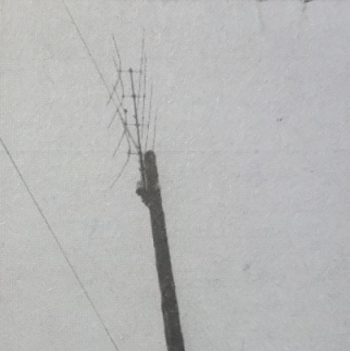
Militärverlag der Deutschen Demokratischen Republik, Berlin 1974
Now it is offical, we have seen bent elements before. So you may think using bent elements is an old hat. Or the mentioned designers just copied from such an old source? Alas, they did not. Maybe such an old photo is animating, but for sure the antenna makers that assembled the shown array did not have optimsing the G/T ratio in mind. • The lower impedance approach by means of anything between roughly 12 and 38 ohms is neither new nor an invention by any post year 2000 Yagi-Designer. Even F9FT has been there with the 21 ele. 432 MHz design and basically all his amateur radio band VHF/UHF Yagi line way back in the 80ths.
Source: Antennes Tonna, Reims, France, 432 MHz 21 elem. Instruction Manual
What he commercalised is the prologue to what we see as todays reinvented 12.5 to 50 ohms Folded Dipole and low impedance intrinsic designs. The band width of the 432 MHz Tonna 19 ele. is pathbreaking too. With a factual impedance of 12.5 ohms, brought to 50 ohms using a folded dipole, it covers the full 10 MHz of the 70 cm band. For that the driver cell is packed quite tightly. Just as with a modern wide band width or high performance concept with best antenna G/T - click . With that concept he was almost there, given he would have had a fast PC to run a NEC program on at hand we would have probably seen a very early milestone. Same would probalby have applied to P. P. Viezbicke way back in the mid 70th if only he had a smart todays Laptop and a copy of EZNEC or 4nec2.
• Bent Dipole?
Now, who was first here? Any K6STI, DG7YBN ... ? And isn't there an 'Inverted Vee' for short wave bands?
 (1) (1)
|
 (2) (2)
|
(1) Source: Rothammel, K., DM2ABK, Antennenbuch, Militärverlag der Deutschen Demokratischen Republik, Berlin 1974, 10.4, Fig. 10.31, pg. 165, Rundstrahlende Dipole (2) Source: Jessop, G. R., G6JP, VHF UHF Manual, Fourth Edition, 1994, Chapter 8.37 - Antennas, Fig. 91, Formation of the omni-V antenna |
No, we have not!
No need to think that the post 2000 designers did not invent anything! In patent pending terms the necessary 'amount of subject matter' describes how much own thinking has been necessary to derive an originally reinvented basic concept into something that will pass the patent survey.Using an effect long known or almost forgotten to the better, a long time past since discovery and/or far better utilisation in unity with deeper understanding make a reinvention to something worthy to be patented. ... like producing a far cleaner radiation pattern and higher Antenna G/T thru the use of a low impedance structure. Which needs combined skills in understanding the Yagi driver cell, wave guiding structure and impedance interaction.
Please do not neglect all progress in Yagi designing, but think when someone claims a certain technique to be something brand new. It might not, but seen in context it very well might be.
And finally an appeal - we're all radio amateurs, interested in new techniques, new antenna designs and what ever. Anyone has ideas of how the ideal Yagi should look like. Some show them, some dislike them. A natural process. Progresses are being made. Errors too. But please, show some respect when dicussing matters. I have read some statements, not only on the moon net reflector, that I would not have ever imagined being issued by radio amateurs against each other.
I wish for fair and factual technical discussions that are confirmed by facts.
73, Hartmut, DG7YBN