-
• Main Page
- • Home
• Antennas - • 432 MHz
- YBN 70-5mA 0.5 m 432 MHz blue print of the YBN 2-5m 50 ohms high F/B direct feed 144 MHz Low Noise Yagi
3D Plot
- YBN 70-14wzTune up your 19 ele. Tonna!
A design based on the hardware of the F9FT, turning it into a 14 ele. OWL with cleaner pattern, +0.3 dB gain and SWR less than 1.2 from 430 to 440 MHz
Azimuth Plot
- GTV 70-2wA 0.14 m GTV useful for portable operation and up to the satellit band and handheld activities of any kind
Elevation Plot
- GTV 70-3wA 0.21 m GTV useful for portable operation and up to the satellit band and lower noise stacks of any kind
Elevation Plot
- GTV 70-4mA 0.34 m GTV useful for portable operation up to the satellit band and lower noise stacks of any kind
Elevation Plot
- GTV 70-7nA 1.1 m 432 MHz blue print of the low impedance, yet 50 ohms direct feed 144 MHz Low Noise Yagi introduced in Dubus 1/2013
Elevation Plot

- GTV 70-9wA 1.44 m GTV ment to be useful as a vertical stack for contesting or be an ideal small size portable Yagi
Elevation Plot
- GTV 70-11wA 2.01 m GTV ment to be useful as a vertical stack for contesting or be an ideal small size portable Yagi or minimum size EME 4 bay
Elevation Plot
- GTV 70-14m2.9 m version of the low impedance, yet 50 ohms direct feed Low Noise Yagi with bent DE introduced in Dubus 1/2013
Elevation Plot
- GTV 70-19m4.2 m version of the low impedance, yet 50 ohms direct feed Low Noise Yagi with bent DE introduced in Dubus 1/2013
Elevation Plot
- GTV 70-23m5.3 m version of the low impedance, yet 50 ohms direct feed Low Noise Yagi with bent DE introduced in Dubus 1/2013
Elevation Plot
- GTV 70-25m5.9 m version of the low impedance, yet 50 ohms direct feed Low Noise Yagi with bent DE introduced in Dubus 1/2013
Elevation Plot
- GTV 70-30m7.3 m version of the low impedance, yet 50 ohms direct feed Low Noise Yagi with bent DE introduced in Dubus 1/2013
Elevation Plot

- YBN 70-5m
23 ele.Yagi by F5JTM with straight Dipole
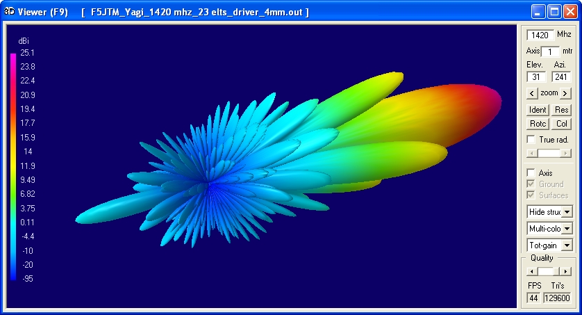
Seti Yagi (1420 MHz) with good side and rear lobe suppression but enough bandwidth for feasible builds
I am proud to host Serge, F5JTM with his low side lobes 23 elem. Yagi design:
Serge does not have an own website but this nice design, so I decided to share a bit of my webspace.
Here is Serge's email address for any requests by other Seti Yagi and Fractals Antennas enthusiasts:
 and link to his Facebook web
Current distribution
Short Screenshot Movie showing rotating 3D Pattern
To watch the rotating 3D Pattern movie by F5JM click here pse
Performance Data
Specs: with 2 mm elements @ 1420 MHz
Gain vs. isotr. Rad.  19.2 dBi
Gain vs. Dipole       17.1 dBD
-3 dB H-plane         21.5 deg.
-3 dB E-plane         22.4 deg.
F/B                  -25.4 dB
F/R                  -25.4 dB
Impedance               50 ohms
Mechan. Length        1877 mm incl. 2 x 30 mm stand off
Electr. Length        8.61 λ

Stacking dist. h-pol.
top-to-bottom         0.54 m or 1.78 ft
side-by-side          0.57 m or 1.85 ft
How many OMs have been looking up this design?
Geometry
Element and Positions on Boom table prepaired by F5JTM:
(Ø 2 mm Elements and Ø 3 mm Dipole)
               Pos.     NEC 1/2 elt   Full Length
Ref.:             0         50.5        101.0
D.E :          45.1         49.5         99.0
D1  :          62.4         47.3         94.6
D2  :         101.6         45.4         90.8
D3  :         148.6         45.0         90.0
D4  :         206.3         44.3         88.6
D5  :         284.7         43.6         87.2
D6  :         369.4         42.9         85.8
D7  :         462.5         42.3         84.6
D8  :         556.4         41.9         83.8
D9  :         648.5         41.5         83.0
D10 :         743.7         41.2         82.5
D11 :         841.0         41.0         82.0
D12 :         941.0         40.5         81.0
D13 :        1035.1         40.2         80.5
D14 :        1138.2         39.9         79.7
D15 :        1239.2         39.6         79.1
D16 :        1338.3         39.3         78.5
D17 :        1436.5         39.0         78.0
D18 :        1534.3         38.6         77.2
D19 :        1633.6         38.3         76.6
D20 :        1724.2         38.0         76.0
D21 :        1817.3         37.7         75.4
Building hints:
For BC valid for microwaves
Elements can be mounted conductive through boom. For a real press fit we heat the boom to maybe +70 C. Then drill holes 2.00 mm or 1.95 mm into the very hot boom. These holes will shrink with decreasing temperature. Then place elements in a deep freezer (-20 C) and push into the hot boom. The element diameter will grow with increasing temperature to ambient numbers. Thus an extra tight press fit can be achieved.
Try with a spare bit of boom and element rods to find right drill hole diameter and temperature handling!
Radiation Pattern and VSWR Plots
Elevation and Azimuth plot at 432.1 MHz
SWR and Return Loss plots - simulated with 4nec2
Downloads
NEC2 (4nec) file of this Yagi with Ø 2 mm ele.
NEC2 (4nec) file of this Yagi with Ø 2 mm ele. as 4bay
Stacking
As on 1420 MHz the Y-factor = T_earth / T_sky is so high, I see little chances to
improve an array's RX performance by using "Over Stacking" distances. However, depending on
the level of local QRM it might be worthwhile to try a decreased distance, especially in the H-plane.
Stacking Dist.    DL6WU Formula
H-plane               0.57 m
E-plane               0.54 m
A 4 bay Yagi stack
Short Screenshot Movie showing rotating 3D Pattern
To watch the rotating 3D Pattern movie by F5JM click here pse
Elevation ad Azimuth plot and data of 4 Yagi bay using DL6WU stacking distances
Gain vs. isotr. Rad.  25.1 dBi
Gain vs. Dipole       23.0 dBD
F/B                  -24.9 dB
F/R                  -24.9 dB
T_ant                 19.6 K (T_pattern = 14.0 K / T_loss = 5.9 K)*
G/T                   12.13 dB*
Theoretical numbers - these do not include phasing line losses
nor imperfections caused by H-frames or mast poles etc.
*) T_sky = 10 K, T_earth = 290 K
Screenshot of TANT for this 4 Yagi stack
Symmetrising 50 to 50 ohms feedline to 1420 MHz DE: 3 x 1/4 λ line
The principle is similar to the 1/4 Lambda coax. Adding 2 x 1/4 λ or a 1/2 λ line does not change anything but allows
to form a gentle bow below the boom or until behind the Reflector. Follow practical construction hints on "Building a Yagi" page.
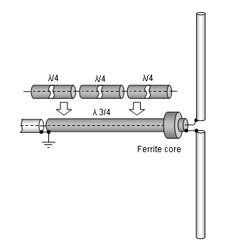
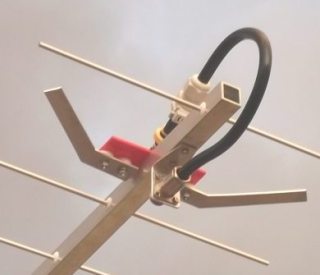
An example for 432 MHz with bent DE
 Attenzione!
Take care when lengthening the coax, measure the actual electrical length instead of considering v-factors specified in a catalogue only.
Attenzione!
Take care when lengthening the coax, measure the actual electrical length instead of considering v-factors specified in a catalogue only.A good choice may be the diam. 5 mm PTFE coax RG-142 B/U: real resonate length (1420 MHz as 3/4 Lambda) shield-shield is around 104 mm
 Find more information on Phasing & Matching Lines page
 73, Hartmut, DG7YBN