-
• Main Page
- • Home
• Antennas - • 432 MHz
- YBN 70-5mA 0.5 m 432 MHz blue print of the YBN 2-5m 50 ohms high F/B direct feed 144 MHz Low Noise Yagi
3D Plot
- YBN 70-8zA 1.5 m high gain 28 ohms Yagi.
A design partly based on the hardware of the WY-7010, turning it into a 8 ele. 28 ohms Yagi with cleaner pattern, +1.8 dB gain and better VSWR.
Azimuth Plot
- YBN 70-14wzTune up your 19 ele. Tonna!
A design based on the hardware of the F9FT, turning it into a 14 ele. OWL with cleaner pattern, +0.3 dB gain and SWR less than 1.2 from 430 to 440 MHz
Azimuth Plot
- YBN 70-14+4wA 3.2 m very wideband 50 ohms Yagi with reflector wall that covers the whole 70 cm band with ease
Elevation Plot
- GTV 70-2wA 0.14 m GTV useful for portable operation and up to the satellit band and handheld activities of any kind
Elevation Plot
- GTV 70-3wA 0.21 m GTV useful for portable operation and up to the satellit band and lower noise stacks of any kind
Elevation Plot
- GTV 70-4wA 0.33 m wideband GTV useful for portable operation up to the satellit band and lower noise stacks of any kind
Elevation Plot
- GTV 70-4mA 0.34 m GTV useful for portable operation up to the satellit band and lower noise stacks of any kind
Elevation Plot
- GTV 70-7wA 0.96 m GTV useful for portable operation up to the satellit band and lower noise stacks of any kind
Elevation Plot
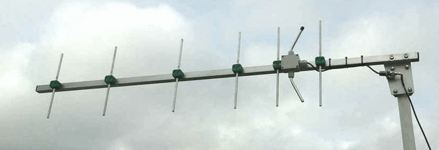
- GTV 70-7nA 1.1 m 432 MHz blue print of the low impedance, yet 50 ohms direct feed 144 MHz Low Noise Yagi introduced in Dubus 1/2013
Elevation Plot

- GTV 70-8nA 1.3 m 432 MHz GTV with high gain but low backlobe volume. Makes a very compact 4 Yagi bay for QRP EME or contesting.
Elevation Plot

- GTV 70-9wA 1.44 m GTV ment to be useful as a vertical stack for contesting or be an ideal small size portable Yagi
Elevation Plot
- GTV 70-10wA 1.63 m GTV useful for portable operation up to the satellit band and lower noise stacks of any kind
Elevation Plot
- GTV 70-11wA 2.01 m GTV ment to be useful as a vertical stack for contesting or be an ideal small size portable Yagi or minimum size EME 4 bay
Elevation Plot
- GTV 70-13mA 2.5 m GTV ment to be useful as a vertical stack for contesting or be an ideal small size portable Yagi or minimum size EME 4 bay
Elevation Plot
- GTV 70-14m2.9 m version of the low impedance, yet 50 ohms direct feed Low Noise Yagi with bent DE introduced in Dubus 1/2013
Elevation Plot
- GTV 70-17m3.7 m version of the low impedance, yet 50 ohms direct feed Low Noise Yagi with bent DE introduced in Dubus 1/2013
Elevation Plot
- GTV 70-18w4.0 m version of the low impedance, yet 50 ohms direct feed Low Noise Yagi with bent DE introduced in Dubus 1/2013
Elevation Plot
- GTV 70-19m4.2 m version of the low impedance, yet 50 ohms direct feed Low Noise Yagi with bent DE introduced in Dubus 1/2013
Elevation Plot
- GTV 70-21n4.7 m version of the low impedance, yet 50 ohms direct feed Low Noise Yagi with bent DE introduced in Dubus 1/2013
Elevation Plot
- GTV 70-23m5.3 m version of the low impedance, yet 50 ohms direct feed Low Noise Yagi with bent DE introduced in Dubus 1/2013
Elevation Plot
- GTV 70-25m5.9 m version of the low impedance, yet 50 ohms direct feed Low Noise Yagi with bent DE introduced in Dubus 1/2013
Elevation Plot
- GTV 70-30m7.3 m version of the low impedance, yet 50 ohms direct feed Low Noise Yagi with bent DE introduced in Dubus 1/2013
Elevation Plot
- GTV 70-34w8.5 m version of the low impedance, yet 50 ohms direct feed Low Noise Yagi with bent DE introduced in Dubus 1/2013
Elevation Plot
- GTV 70-46w12.0 m version of the low impedance, yet 50 ohms direct feed Low Noise Yagi with bent DE introduced in Dubus 1/2013
Elevation Plot
- DL6WU YagisThe DL6WU Longyagi Series
Sample plot: 32 el. plus 4 x reflector
Elevation Plot

- YBN 70-5m
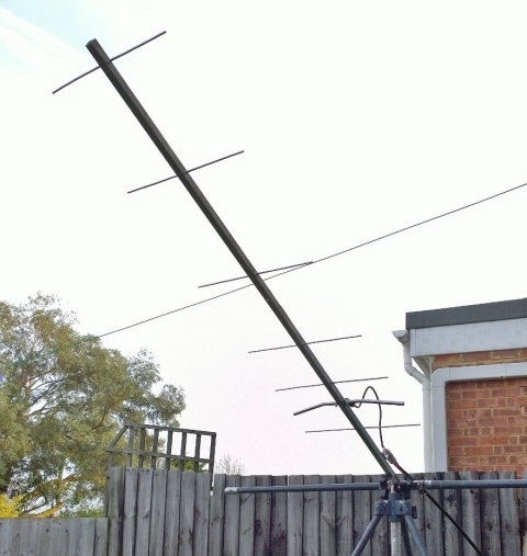
GTV 70-7n Yagi with bent Driven Element
EME + SSB narrow bandwidth version ... strictly G/T breeding
This little Yagi has a high F/B, which makes it quite useful as a contest stack
The bent DE (K6STI style) transforms from approx. 17 ohms to 50 ohms at feed point.
You might also take a look at the only 40 cm longer GTV 70-9w, which should be less
demanding in absolute dimensioning.
 The GTV 70-7n is EME tested in many QSOs
In case you have never build a Yagi with bent DE for 432 MHz before or have little experience
in home brewing Yagis in general ... or simply want to achieve top performance ...
I strongly recommend to build this little 7 ele. as a Test-Yagi to find the exact BC and learn how
to trim the bent DE for best VSWR on this pocket version before moving to a long boomer. It was
my prime intention to give you a practicable narrow band width Test-Yagi at hand when I enclosed
it in the Dubus Article introducing the GTV Long Yagi series.
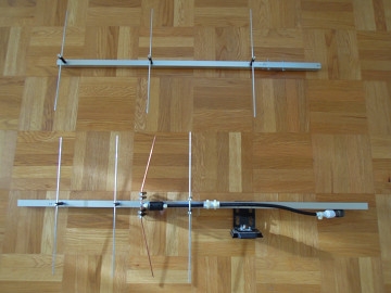
• 2x vertical stack of GTV 70-7n built by Maxime, F4FEY

• GTV 70-7n built by Jürgen, DF3OL


• GTV 70-7n built by Thomas, M0ABA for use at MX0CNS for demonstrating QRPP 70 cm EME
and a Microset Preamp with built in coax relays only:


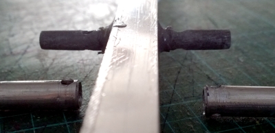
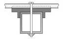
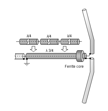
pushed onto a plastic center piece, which is 'pierced' through the boom. The symmetrising Quarterwave line is
made from Aircom 5 with a ferrite core right at the split point where it connects to the dipole.
Here are photos of the dipole arms mount - a plastic rod that is pushed through the boom. This construction
enables a zero offset between dipole and element plane when using elements through boom.
I have described such a dipole mount with a few sketches here
• Take a look at photos explaining how to build this Yagi on the GTV 70-4m website


• GTV 70-7n modified for the 403-406 MHz Radio Sonde Band built by F4GRT
Philippe, F4GRT reports his first impressions
"Today I could decode the position of a radiosonde at 550 km (the Balearics) from my QRA and another also
at 550km at Saragossa (Spain). I am at Salon de Provence, 50km from Marsille. The emitting power of the
radiosonde was only 100mW. The antenna impedance is 50 + j0 ohms and SWR is of 1.01:1 in the center of the
403-406 MHz band."
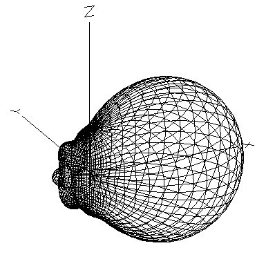
Current Distribution & 3D pattern


• A lightweight GTV 70-7n built by Kazuo, 7L1TIG
First image: comparing to K1FO 8 ele. Yagi with good result. Note the stand off insulators held by an acryl glass plate.

In a later version (Jan. 2015) the bent dipole is made from 10 x 2 mm sheet metal, which helped to better Return Loss > - 30 dB

Photos: with kind permission of Kazuo, 7L1TIG
Find a VSWR chart further down on this website.
See his website about Amateur Radio with focus on 430 MHz antennas for portable use (in Japanese)
Kazou made a whole set of websites about small DG7YBN Yagis, all redesigned in MMANA for 430-431 MHz.
A very clear and methodic work. I recommend this to read. Use a free website online translator.
• See the amazing portable version build by 7M2MZO (in Japanese) here
This website has been viewed by how many 70 cm enthusiasts since Jan. 2016?
Performance Data
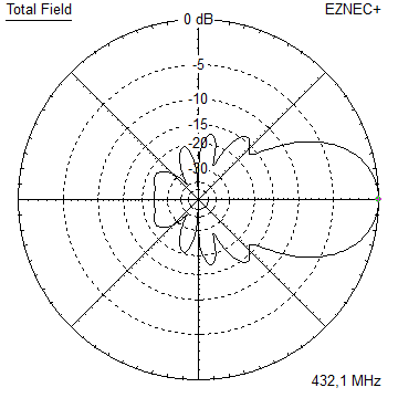
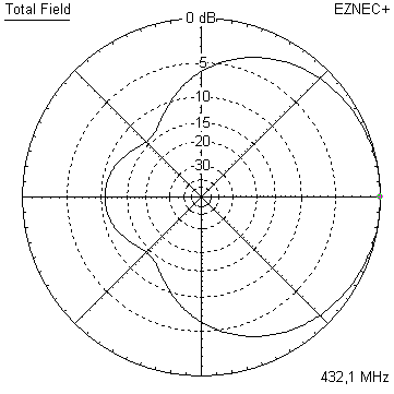
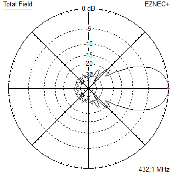
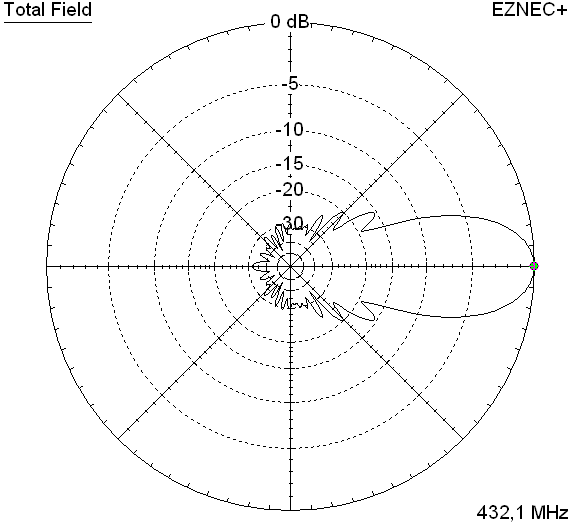
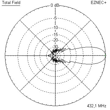
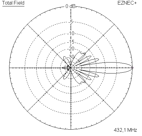
Gain vs. isotr. Rad.  12.9 dBi
Gain vs. Dipole       10.8 dBD
-3 dB E-plane         41.4 deg.
-3 dB H-plane         48.4 deg.
F/B                  -29.4 dB
F/R                  -21.9 dB
Impedance               50 ohms
Mechan. Length        1012 mm
Electr. Length        1.46 λ

Stacking Dist. h-pol.
top-to-bottom         0.85 m
side-by-side          0.98 m
Geometry
The 8 mm element geometry data are to fit On-Boom-with-Standard-Insulators style of building.
The 4 mm elements are ment for an 'elements through boom' built.
Segmentation BC and Base BC (see BC page) must be added.
A simple symmetrising member may be made from a 3 x 1/4 Lambda line grounded at the far side with
N-flange-bushing and an aluminium plate and ferrite added as close as possible to the DE, see below.
        Pos.    Full Length      1/2 Length    1/2 Length
                                   in NEC

Refl.     0        330.0           163.0          162.0
DE(b)  80/78       296.0        33.5-148.7     33.5-148.3
DE(a)   110         67.0          0-33.5         0-33.5
D1      172        313.0           154.5          152.0
D2      307        308.0           151.0          149.0
D3      523        300.0           147.0          144.5
D4      785.5      292.0           143.0          140.0
D5     1016        281.0           136.5          133.5
                 ele. 4 mm       ele. 1/4"      ele. 8 mm
The Drivers diameter is 10 mm for all examples.
Use EZNEC's Auto-Segmentation at 1050 MHz.
For the SBC the frequency impact is 433.55 MHz - 432.10 MHz = 1.45 MHz
Multiplication with the 70 cm correction factor of 0.92 mm/MHz results in 1.33 mm to add to the common BC.
Table 1: GTV 70-7n, 8 mm elements on boom:
• "Ready to saw and drill" data for mounting 8.0 mm elements on boom with standard insulators on 20 x 20 mm boom including a 30 mm offset from booms end:
This table is valid for:
Boom shape: square
Boom dim: 20 x 20 mm
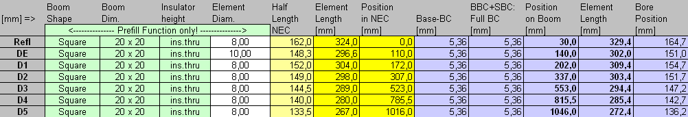
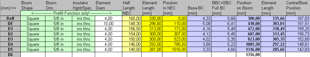
Table 2 + 3: GTV 70-7n, 4 mm elements through boom:
"Ready to saw and drill" data for mounting elements through boom with BC according SM5BSZ's BC.exe:
Note: with through Boom BC it is important to stick to the boom end offsets given below!
Imperial Boom 5-8"
|
Boom shape: square Boom dim: 5/8 in x 5/8 in (15.9 mm) Wall thickn.: 1.6 mm Holes in boom: 6.0 mm Offset rear: 40 mm Offset front: 40 mm |
|

Note: with through Boom BC it is important to stick to the boom end offsets given below!

• Same data set for 4 mm elements as above, but with rear boom end offset = 300 mm for formast mounting
|
Boom shape: square Boom dim: 5/8 in x 5/8 in (15.9 mm) Wall thickn.: 1.6 mm Holes in boom: 6.0 mm Offset rear: 300 mm Offset front: 40 mm |
|
Sketch of Bent Dipole

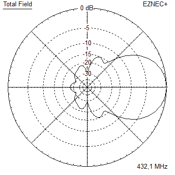
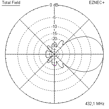
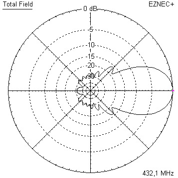
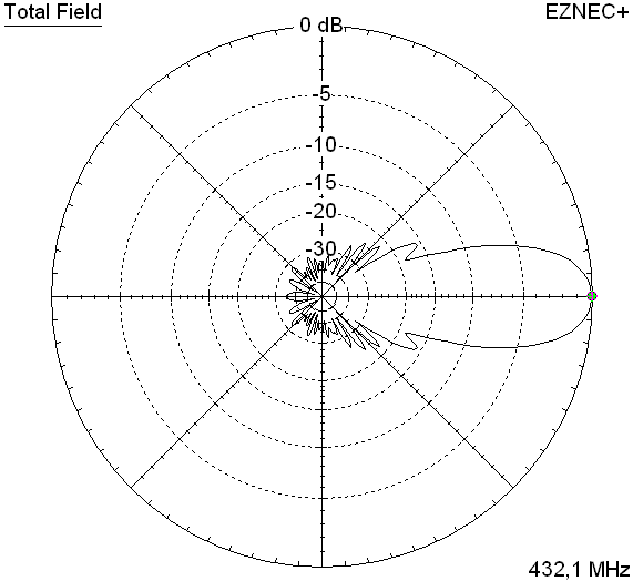
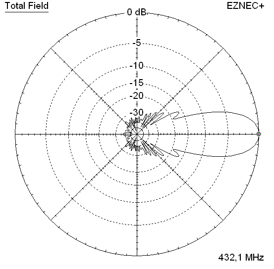
Pattern and VSWR Plots
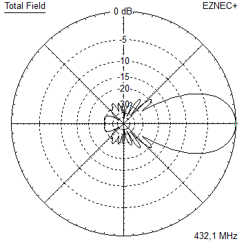
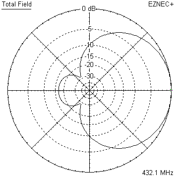
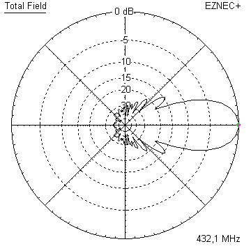
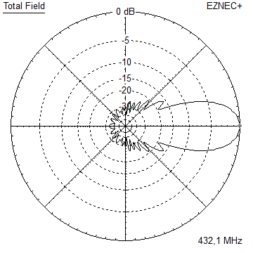
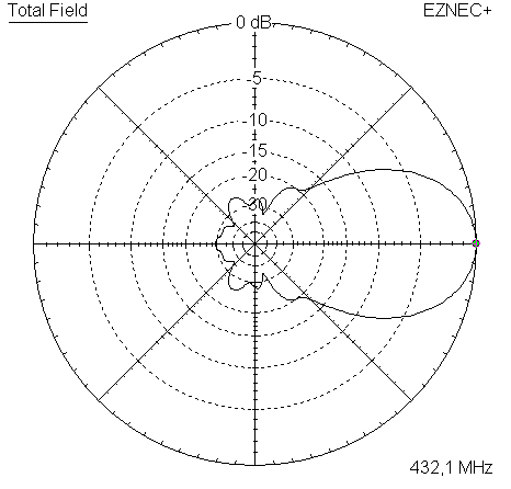
Elevation and Azimuth plot at 432.1 MHz

RL and SWR plot

Simulated and real world VSWR of 7L1TIG's lightweight build (a version remodelled in MMANA)

Downloads
EZNEC file of this Yagi with Ø 1/4" elements
EZNEC file of this Yagi with Ø 8 mm elements
EZNEC file of this Yagi with Ø 4 mm elements
CSV file for the Yagi Element Configuration Tool with 4 mm elements
Stacking
As on the 432 MHz Band the Y-factor = T_earth / T_sky is that high I see little chances in
bettering an array's RX performance by using "Over Stacking" distances. However, depending
the level of local QRM it might be worthwhile to try less distance, especially in H-plane.

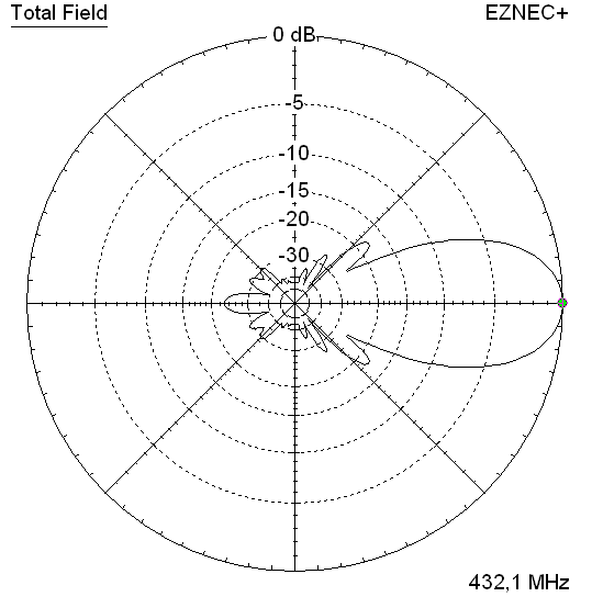
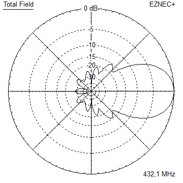
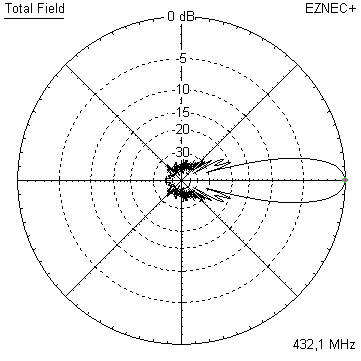
4 x GTV 70-7n bay - a very compact array
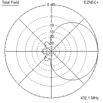
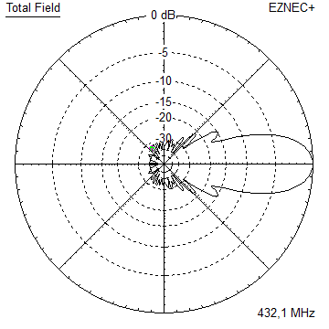
Gain vs. isotr. Rad.  18.8 dBi
Gain vs. Dipole       16.7 dBD
-3 dB H-plane         13.2 deg.
-3 dB E-plane         10.4 deg.
F/B                  -33.6 dB
F/R                  -26.3 dB
T_ant                 36.2 K*
G/T                   3.25 dB*

Theoretical numbers, no phasing line losses
nor imperfections caused by mast included
*) T_sky = 20 K, T_earth = 350 K as in VE7BQH G/T table
Stacking Dist.    DL6WU Formula
H-plane               0.85 m
E-plane               0.98 m
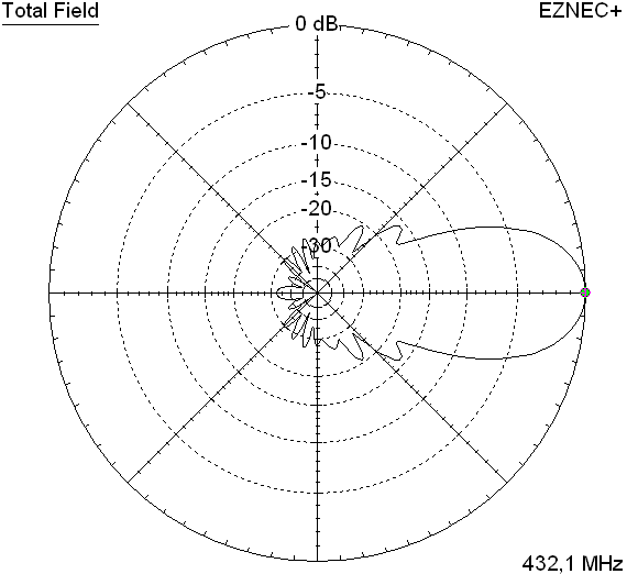
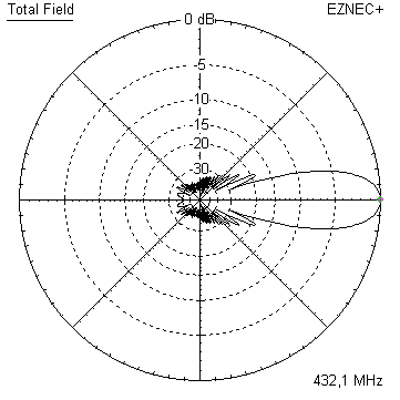
Elevation plot and data of 4 Yagi stacked vertically using DL6WU stacking distances
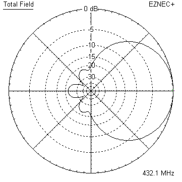
Gain vs. isotr. Rad.  18.8 dBi
Gain vs. Dipole       16.7 dBD
-3 dB H-plane         13.2 deg.
-3 dB E-plane         41.8 deg.
F/B                  -33.6 dB
F/R                  -26.3 dB
Symmetrising 50 to 50 ohms Feedline to 432 MHz Bent DE
The principle is similar to the 1/4 Lambda coax. Adding 2 x 1/4 Lambda or a half wave line does not change anything but allows
to form a gentle bow below the boom or until behind the Reflector. Follow practical construction hints on "Building a Yagi" page.
 Attenzione!
Take care when lengthening the coax, measure the right length instead of refering to given v-factors only.
Attenzione!
Take care when lengthening the coax, measure the right length instead of refering to given v-factors only.A good choice may be the diam. 5 mm PTFE coax RG-142 B/U: real resonate length (432.2 Mhz as 3/4 Lambda) shield-shield is around 348 mm
 Find more information on Phasing & Matching Lines page
 73, Hartmut, DG7YBN