-
• Main Page
- • Home
• Antennas - • 432 MHz
- YBN 70-5mA 0.5 m 432 MHz blue print of the YBN 2-5m 50 ohms high F/B direct feed 144 MHz Low Noise Yagi
3D Plot
- YBN 70-8zA 1.5 m high gain 28 ohms Yagi.
A design partly based on the hardware of the WY-7010, turning it into a 8 ele. 28 ohms Yagi with cleaner pattern, +1.8 dB gain and better VSWR.
Azimuth Plot
- YBN 70-14wzTune up your 19 ele. Tonna!
A design based on the hardware of the F9FT, turning it into a 14 ele. OWL with cleaner pattern, +0.3 dB gain and SWR less than 1.2 from 430 to 440 MHz
Azimuth Plot
- YBN 70-14+4wA 3.2 m very wideband 50 ohms Yagi with reflector wall that covers the whole 70 cm band with ease
Elevation Plot
- GTV 70-2wA 0.14 m GTV useful for portable operation and up to the satellit band and handheld activities of any kind
Elevation Plot
- GTV 70-3wA 0.21 m GTV useful for portable operation and up to the satellit band and lower noise stacks of any kind
Elevation Plot
- GTV 70-4mA 0.34 m GTV useful for portable operation up to the satellit band and lower noise stacks of any kind
Elevation Plot
- GTV 70-7wA 0.96 m GTV useful for portable operation up to the satellit band and lower noise stacks of any kind
Elevation Plot
- GTV 70-7nA 1.1 m 432 MHz blue print of the low impedance, yet 50 ohms direct feed 144 MHz Low Noise Yagi introduced in Dubus 1/2013
Elevation Plot
- GTV 70-8nA 1.3 m 432 MHz GTV with high gain but low backlobe volume. Makes a very compact 4 Yagi bay for QRP EME or contesting.
Elevation Plot

- GTV 70-9wA 1.44 m GTV ment to be useful as a vertical stack for contesting or be an ideal small size portable Yagi
Elevation Plot
- GTV 70-10wA 1.63 m GTV useful for portable operation up to the satellit band and lower noise stacks of any kind
Elevation Plot
- GTV 70-11wA 2.01 m GTV ment to be useful as a vertical stack for contesting or be an ideal small size portable Yagi or minimum size EME 4 bay
Elevation Plot
- GTV 70-13mA 2.5 m GTV ment to be useful as a vertical stack for contesting or be an ideal small size portable Yagi or minimum size EME 4 bay
Elevation Plot
- GTV 70-14m2.9 m version of the low impedance, yet 50 ohms direct feed Low Noise Yagi with bent DE introduced in Dubus 1/2013
Elevation Plot
- GTV 70-17m3.7 m version of the low impedance, yet 50 ohms direct feed Low Noise Yagi with bent DE introduced in Dubus 1/2013
Elevation Plot
- GTV 70-18w4.0 m version of the low impedance, yet 50 ohms direct feed Low Noise Yagi with bent DE introduced in Dubus 1/2013
Elevation Plot
- GTV 70-19m4.2 m version of the low impedance, yet 50 ohms direct feed Low Noise Yagi with bent DE introduced in Dubus 1/2013
Elevation Plot
- GTV 70-21n4.7 m version of the low impedance, yet 50 ohms direct feed Low Noise Yagi with bent DE introduced in Dubus 1/2013
Elevation Plot
- GTV 70-23m5.3 m version of the low impedance, yet 50 ohms direct feed Low Noise Yagi with bent DE introduced in Dubus 1/2013
Elevation Plot
- GTV 70-25m5.9 m version of the low impedance, yet 50 ohms direct feed Low Noise Yagi with bent DE introduced in Dubus 1/2013
Elevation Plot
- GTV 70-30m7.3 m version of the low impedance, yet 50 ohms direct feed Low Noise Yagi with bent DE introduced in Dubus 1/2013
Elevation Plot
- GTV 70-34w8.5 m version of the low impedance, yet 50 ohms direct feed Low Noise Yagi with bent DE introduced in Dubus 1/2013
Elevation Plot
- GTV 70-46w12.0 m version of the low impedance, yet 50 ohms direct feed Low Noise Yagi with bent DE introduced in Dubus 1/2013
Elevation Plot
- DL6WU YagisThe DL6WU Longyagi Series
Sample plot: 32 el. plus 4 x reflector
Elevation Plot

- YBN 70-5m
GTV 70-14m Yagi with bent Driven Element
EME + SSB band, with some loss usable for FM up to 435 MHz
This Yagi has very low back lobes for its length. It may serve as single antenna for Tropo or even a very compact EME bay.
It also makes a quiet contest antenna due to its high F/B. The bent DE (K6STI style) transforms from approx. 17 ohms to 50 ohms at feed point. Date of issue of design: 2013.01.31
There is a new drawing available showing the unique 'Blade DE' as introduced in Dubus 4/2014,
see Download Area. For making of a 'Blade Dipole' see here
Current distribution
GTV 70-14m built by KI6WJ

GTV 70-14m built by G1YFG


Blade Dipole is this
Photo and S11 Plot Credits: Robin, G1YFG (tnx!)
2 x GTV 70-14m built by 2M0ETJ

Glyn reports: Initial VSWR, no tuning: 1:1.05
GTV 70-14m as v-plane in a GTV70-25m built by ZS6JON
However extensive testing needs to be done on a 70 cm Cross Yagi like this before
we can say it is a good solution ... Return Loss both planes look alright and do
not affect each other but now real RX and TX performance must be tested and judged.
I will report here or scrap this as an xpol design if no good.


GTV 70-14m built by G3LGR

In addition, it is significantly quieter at this location and allows me to see some 3 S points of sun noise on my IC910H."
Some details: He uses a standard SSB 70cm preamp with a noise figure of 0.8 dB. Symmetrising is done through a simplified EMI stub
here with VSWR 1.1 or less. The Yagi is built on 20 x 20 mm boom with 8 mm elements on boom with insulators and M3 screws
as sold by 7arrays
Stations worked by Mike, G3LGR so far with 80 W and this single GTV 70-14:
DF3RU, DK3WG, DL6SH, DL7APV, HB9Q, I1NDP, JA6AHB, LZ1DX, NC1I,
OH2PO, OK1DFC, OK1KIR, PI9CAM, UA3PTW, VK4EME
The Blade Dipole GTV Yagi arrives Stateside: AE7OV's 4 x GTV 70-14m:
GTV 70-14m built by Gary, AE7OV using the Imperial Measure Table below,
3/4 λ symmetrising line from LMR 400 (405 mm to N-flange), Blade Dipole
as per drawing in Download section.

He did first EME QSOs with nothing but an FT-847 (50 W out) and DEMI kit LNA only now.

Performance Data
Specs: with 8 mm elements @ 432.1 MHz
Gain vs. isotr. Rad.  16.38 dBi
Gain vs. Dipole       14.2 dBD
-3 dB E-plane         29.2 deg.
-3 dB H-plane         30.8 deg.
F/B                  -33.0 dB
F/R                  -26.9 dB
Impedance               50 ohms
Mechan. Length        2820 mm
Electr. Length        4.06 λ

Stacking Dist. h-pol.
top-to-bottom         1.306 m
side-by-side          1.376 m
How often has this antenna been looked up since early June 2015?
Geometry
Metrical Measures
EZNEC Wires for 8 mm Elements

Table 1: "Ready to saw and drill" data for mounting 8 mm elements on a 20 x 20 mm boom with standard insulators including BC according DG7YBN

Table 2: "Ready to saw and drill" data for mounting 10 mm elements on a 25 x 25 mm boom with standard insulators including BC according DG7YBN

Table 3: GTV 70-14m, 4 mm elements through a 20 x 20 mm boom:
"Ready to saw and drill" data for mounting elements through boom with BC according SM5BSZ's BC.exe:
|
This table is only valid for: Boom shape: square Boom dim: 20 x 20 mm Wall thickn.: 2.0 mm Holes in boom: 6.0 mm Offset rear: 40 mm Offset front: 40 mm |
|

Note: This includes a "Segmentation Density Correction" (SBC) of 1.19 mm plus an offset of 0.70 mm per element = 1.89 mm
for compensation of the insulators (7arrays.com
Note: Other insulators will need other offset, with their length being probably the most important parameter for this.
Thus I advise to cut other plastic insulators to 7 mm each to match at least the length of the pilot insulators.
Note: with through Boom BC it is important to stick to the boom end offsets given below!
Read abt. the SBC here
Imperial Measures
Table 1: GTV 70-14m, 3/16 inch elements through a 1 x 1 inch boom:
 <= NEC Geometry 3/16" = 4.735 mm ele. insulated through boom (BC must be added)
Building data derived employing SM5BSZ BC.exe formulas with Imperial Measures Material and elements mounted insulated through boom:
Boom 1x1 in, ele. 3/16 in, plastic hole plugs - outer diam. 0.24 in, length along element 7.9 mm
"Ready to saw and drill" data for mounting elements through boom with BC according SM5BSZ's BC.exe:
Note: with through Boom BC it is important to stick to the boom end offsets given below!
This table is only valid for:
Boom shape: square
Boom dim: 1 x 1 in
Wall thickn.: 1.5 mm
Holes in boom: 6.1 mm
Offset rear: 30 mm
Offset front: 30 mm
Note: This includes a "Segmentation Density Correction" (SBC) of 1.37 mm derived from f_seg(1050 MHz) = 432.2 MHz vs f_seg(432 MHz)
= 433.7 MHz plus an offset of 0.79 mm total to cover both plastic plugs influence. The total offset is 2.16 mm then.

Thus I advise to cut other plastic insulators to 7 mm each to match at least the length of the pilot insulators.

Using a large calliper gauge to control lenghts to the 10th of a millimeter is a must.
Table 2: GTV 70-14m, 4 mm elements through a 1 x 1 inch boom:
"Ready to saw and drill" data for mounting elements through boom with BC according SM5BSZ's BC.exe:
|
This table is only valid for: Boom shape: square Boom dim: 1 x 1 inch Wall thickn.: 1/16 inch = 1.6 mm Holes in boom: 6.0 mm Offset rear: 40 mm Offset front: 40 mm |
|
Note: This includes a "Segmentation Density Correction" (SBC) of 1.19 mm plus an offset of 0.70 mm per element = 1.89 mm
for compensation of the insulators (7arrays.com
Note: Other insulators will need other offset, with their length being probably the most important parameter for this.
Thus I advise to cut other plastic insulators to 7 mm each to match at least the length of the pilot insulators.
Note: with through Boom BC it is important to stick to the boom end offsets given below!
Read abt. the SBC here

Using a large calliper gauge to control lenghts to the 10th of a millimeter is a must.
The Drivers diameter is 10 mm for all examples.
Use EZNEC's Auto-Segmentation at 1050 MHz.
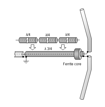
A simple symmetrising member may be made from a 3 x 1/4 Lambda line grounded at the far side with
N-flange-bushing and an aluminium plate and ferrite added as close as possible to the DE, see below.
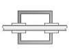
Sketch of Bent Dipole
Pattern and VSWR Plots
Elevation and Azimuth plot at 432.1 MHz


SWR and Return Loss plots - simulated with 4nec2


Downloads
Elem. 8 mm: EZNEC file of this Yagi
Elem. 3/16 in: EZNEC file of this Yagi

Drawing of this Yagis 'Blade' Dipole in 2 mm aluminium sheet metal

Sketch of Blade DE on Boom

*) acc. to what is given in the related table
Stacking
As on the 432 MHz Band the Y-factor = T_earth / T_sky is that high I see little chances in
bettering an array's RX performance by using "Over Stacking" distances. However, depending
the level of local QRM it might be worthwhile to try less distance, especially in H-plane.

Stacking Dist.    DL6WU Formula
H-plane               1.38 m
E-plane               1.31 m
Elevation plot and data of 4 Yagi bay using DL6WU stacking distances


Gain vs. isotr. Rad.  22.3 dBi
Gain vs. Dipole       20.2 dBD
-3 dB H-plane         13.2 deg.
-3 dB E-plane         14.0 deg.
F/B                  -33.3 dB
F/R                  -27.5 dB
T_ant                 74.3 K*
G/Ta                  3.60 dB*
Theoretical numbers, no phasing line losses
nor imperfections caused by H-frame included
*) T_sky = 27 K, T_earth = 1800 K as in VE7BQH Antenna Table, issue 22
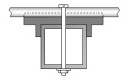
Symmetrising 50 to 50 ohms Feedline to 432 MHz Bent DE
The principle is similar to the 1/4 Lambda coax. Adding 2 x 1/4 Lambda or a half wave line does not change anything but allows
to form a gentle bow below the boom or until behind the Reflector. Follow practical construction hints on "Building a Yagi" page.
 Attenzione!
Take care when lengthening the coax, measure the right length instead of refering to given v-factors only.
Attenzione!
Take care when lengthening the coax, measure the right length instead of refering to given v-factors only.A good choice may be the diam. 5 mm PTFE coax RG-142 B/U: real resonate length (432.2 Mhz as 3/4 Lambda) shield-shield is around 348 mm
 Find more information on Phasing & Matching Lines page
 73, Hartmut, DG7YBN