• Main Page
- • Home
• Antennas
- • 144 MHz
- Bent dipole GTV
144 MHz YagisGTV 2-7w: 2.7 m wide band width version of the low impedance, yet 50 ohms
direct feed Low Noise Yagi with bent DE introduced in Dubus 1/2013 Elevation Plot

- YBN 3+7 SAT
A Satellite Yagi with 3 ele. for 145 MHz + 7 ele. for 435 MHz for handheld use
Elevation Plots
- YBN 2-2w
A 50 ohms direct feed 2 ele. Yagi with high potential
as broad beam Contest Stack. See yourself and compare to DJ9HO Double Quads and 7ZB Oblongs. Full details on 2 and 4 Yagi
stacks are given 3D Pattern of 4 x Stack

- YBN 2-5m (5-8)
1.6 m high F/R, good willing 50 ohms
direct feed Yagi as introduced with bent DE short version of the 5-8 in Dubus 4/2012 Elevation Plot
- YBN 2-6m
1.9 m long, good willing 50 ohms
direct feed Yagi, related to the 5-8 project (same positions refl, dipole, D1, D2 ... same size folded dipole) Elevation Plot

- YBN 2-7m
2.8 m high F/R, good willing 50 ohms
direct feed Yagi, related to the 5-8 project (same positions refl, dipole, D1, D2 ... same size folded dipole) Elevation Plot

- YBN 2-7mz 28 Ω
2.8 m high F/R, good willing 28 ohms
direct feed Yagi Elevation Plot
- YBN 2-8m (5-8)
3.6 m nice G/T, good willing 50 ohms
direct feed Yagi as introduced with bent DE expanded version of the 5-8 in Dubus 4/2012
Actually it seems to be so good that DK7ZB decided to use it as draft for the 8 ele. OWM he just published.
Elevation Plot
- YBN 2-8mz 28 Ω
3.6 m 25/28 ohms version of the YBN 2-8m
The stacked 25 ohms Yagi can easily be phased with 50 ohms coax cables
Elevation Plot

- YBN 2-9mz 28 Ω
4.3 m high F/R, high G/Ta 28 ohms Yagi
Elevation Plot

- YBN 2-9m
4.5 m moderate band width, low Antenna Temperature, good willing 50 ohms
direct feed Yagi - a straigh DE version twin to the GTV 2-9m
Elevation Plot
- YBN 2-10w (5-8)
5 m wide band, good willing 50 ohms
direct feed Yagi as introduced with straight DE expanded version of the 5-8 in Dubus 4/2012
Elevation Plot
- YBN 2-10wz 12.5Ω
5.1 m - 144.0 to 144.8 MHz wide band 12 ohms OWL-style
Low Noise Yagi with straight DE and very low back lobes only Elevation Plot

- YBN 2-12wz 12.5Ω
6.8 m wide band 12 ohms OWL-style
Low Noise Yagi with straight DE and very low back lobes only Azimuth Plot:
|
....... |
 
 
 Performance Data and Geometry Performance Data and Geometry
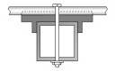
Sketch of Boom
Pattern and VSWR
Crossyagi - xpol configuration
FM Version with Folded Dipole new
Download as File
Stacking
YBN 2-8m Yagi with Conventional Driver (Split or Folded Dipole)
This little Yagi has a high F/B, which makes it quite useful as a contest stack.
The 8 elem. YBN 2-8m version is the prolonged 5 ele. YBN 2-5m. It uses same Driver Cell elements and dipole.
Thus one can swap between various setups like 5 over 5 to 4 x 8 elem. or to 4 x 5 ele. vertically very easily.
Just as time, place and WX conditions demand. Read the full text in Dubus magazine issue 4/2012.
The YBN 2-10w is the final stage of expansion from YBN 2-5m > YBN 2-8m > YBN 2-10w with same Driver Cell.
Current distribution

References please?
The YBN 5-8 seems to have become quite popular to reference other Yagis or serve as base for own design modifications.
We see DK7ZB modifying it to 28 ohms (8-El.-2m-OWM-Yagi) by just changing elements in driver cell and G4CQM compare it to his CQM8C4 design.
Just keep in mind that I wanted the 5-8 to be a very uncritical conventional design and ever planed it to be part of the expandable 5-8 concept.
Which means that the 5 ele. can be expanded to this 8 ele. without modifications to the driver cell and re-using as many elements as possible
Hence it is limited to the needs of that concept, yet capable to be a serious player in the G/T table. The fact that other designers love to
refer to it shows its abilities. A pair of vertical stacks of YBN 2-8 helped 7S7V to a win in the 6 h class of the 2017 Marconi Memorial Contest.
2 x 8 YBN 2-8m at 9A6C

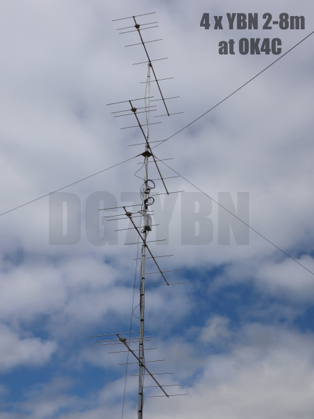
A total of 4 pieces of vertical stacks of 4 x 8 YBN 2-8m at OK4C in 2023 IARU Region 1 ctest


Zdenek, OK1DSZ on behalf of the team of OK4C reports:
"Once again thanks for your support, your antennas work excellent. This summer additional 12 yagis were built,
no tuning needed, it always sits in the band, no need for any further adjustment.
"
Link to OK4C website with full report on the IARU 1 ctest 2023, lots of photos and video
4 x vertical stack of YBN 2-8m at OK4C in 2022 IARU Region 1 ctest
Zdenek, OK1DSZ on behalf of the team of OK4C reports:
"The stack, installed on a 15 m tower, was first used this past weekend in the VHF contest.
We took part as OK4C from one of the best locations in the country, Klinovec hill, close the OK/DL
border north of Carlsbad, JO60LJ, 1244 m asl. This stack was most of the time used to cover
the JO31/ON/PA/G area, and it worked wery well. In total we made 1009 qsos, 366kpoints."
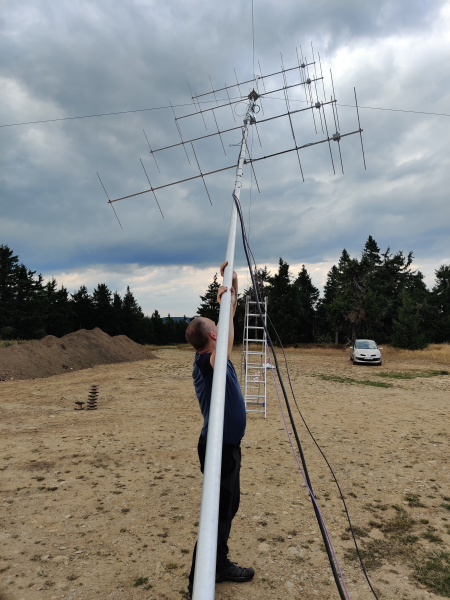
On right photo ... full antenna setup: 4 x 8 el.,4 x 7 el., 2 x 11 el., 2 x 10 el., 18 el.,11 el.
Link to OK4C website for more details and video.
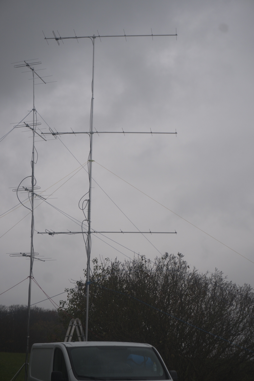
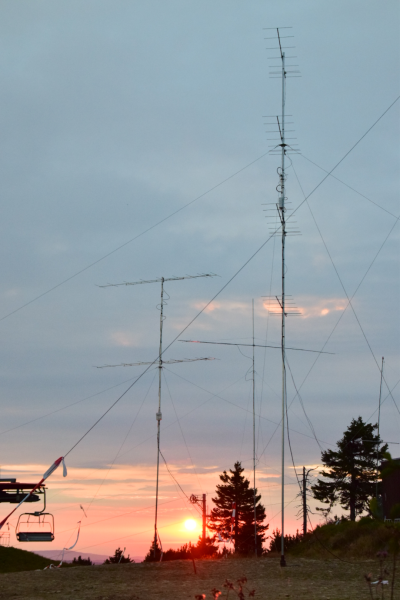
3 x vertical stack of YBN 2-8m at 7S7V in 2021 IARU Region 1 ctest
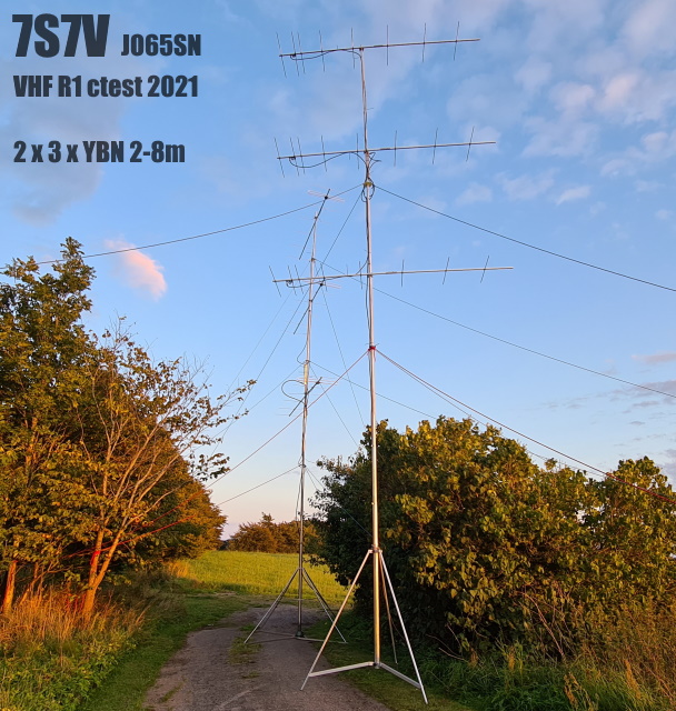
YBN 2-8m with straight dipole by Antennas-Amplifiers at VSWR test by Samir, 7S7V

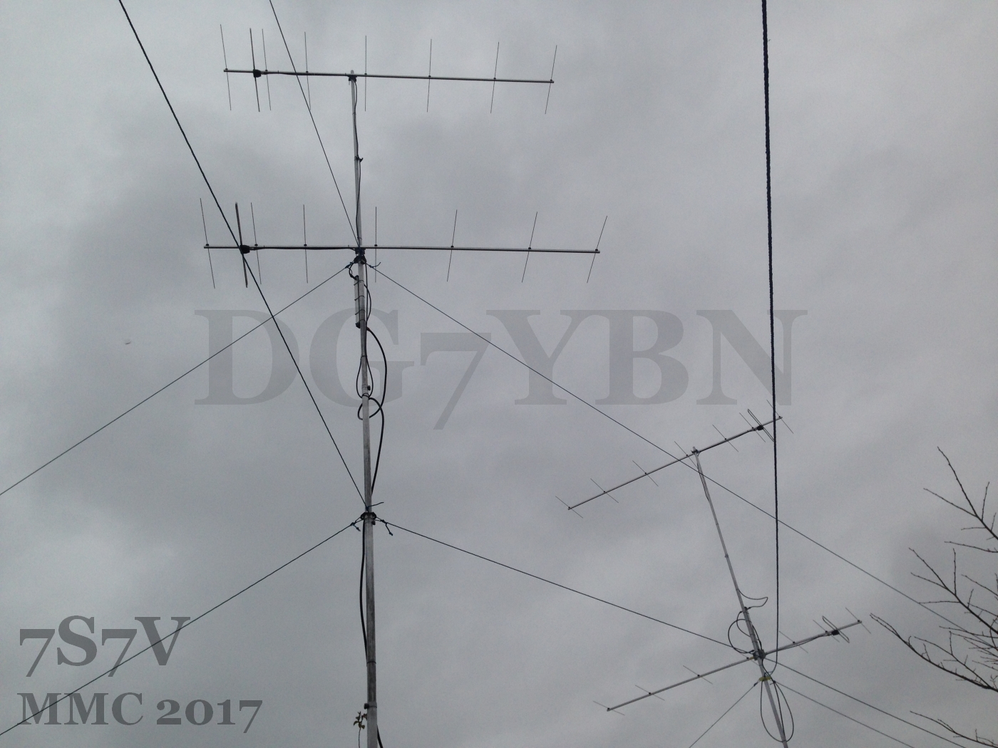
7S7V : Winner of Marconi Memorial Contest 2017 - Single OP, 6 hours
Contest Station 7S7V from Malmö using 2 x 2 vert. YBN 2-8m with Folded Dipole
in MMC 2017: Congrats Samir! Click on Images to enlarge
This Yagi is built on 20 x 20 mm boom, ready made folded dipole by Co. WiMo, 5 mm elem. on SM7DTT insulators, s. here


DX Report by F4EZJ, Stef
During the 21.-25.Oct. 2018 Tropo-Opening and Perseids Stef placed a vertical stack of 2 x YBN 2-8m set up into his garden.
Feeding 500 W he did very nice QSOs:
Top SSB OSOs Tropo-Opening 21.-25.Oct. 2018

DH8BQA   JO73CE   1322 km
EI9KP    IO54MB   1164 km
GM4PPT   IO75SK   1161 km
EI3GYB   IO53OT   1136 km

plus a number of QSOs in FT8 > 1300 km


Top OSOs Perseids 2018

EA8TX   IL18QI  2412 km
SM5DWF  JP90JA  2029 km
LY2FN   KO14XV  1972 km
YL2AO   KO16DK  1952 km

F4EZJ/p, Stef used 2 single and a 2 x vertical stack of YBN 2-8m's and along 4 x vertical 5 ele. LFA
in Championat de France THF 2016 contest: and finished "with 355 QSOs ... antennas doing excellent!!!"

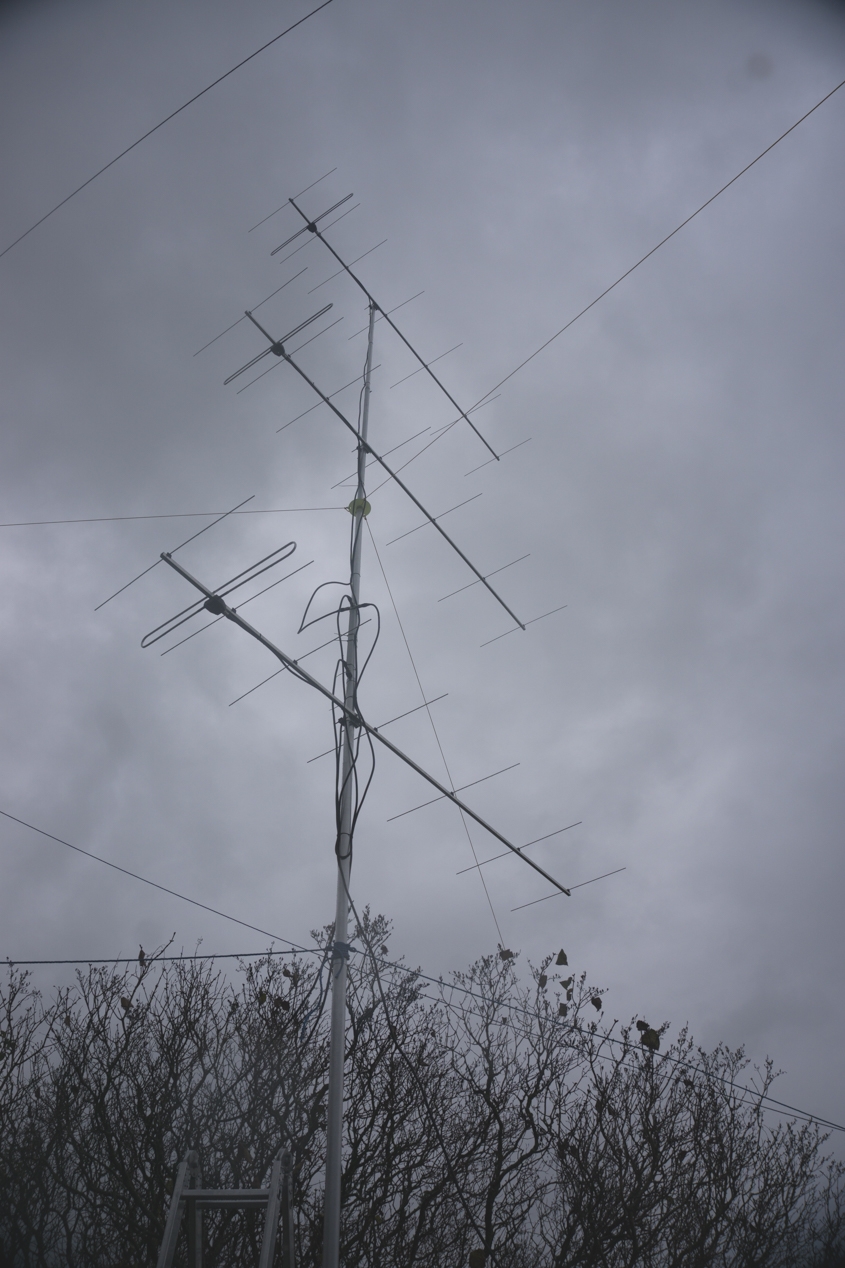
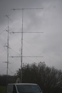
Contest Station 7S7V from Malmö using 3 x vert. YBN 2-8m with Folded Dipole
in MMC 2016: Click Images to enlarge


DG7YBN/p Functional Check: Two hours Hoher Meissner & VHF Region 1 ctest

Does this design perform?

YBN 2-8m, FT-736R, 15 m RG213, 680 m ASL in SSB
Saturday afternoon in IARU VHF 2013, in nill cndx

IK1WVQ     769 km        Troposcatter, across the
IK3UNA/P1  725 km        Alps with 25 W only
G8T        626 km ...    Avg. QRB 490 km, 15 QSOs
|

|
Performance Data
                        Elem. 4 mm       Elem. 5 mm      Elem. 8 mm
Gain vs. isotr. Rad.   13.0/13.1 dBi      13.1 dBi        13.1 dBi
Gain vs. Dipole        10.8/10.9 dBD      10.9 dBD        10.9 dBD
-3 dB E-plane            42.0 deg.        41.8 deg.       41.8 deg.
-3 dB H-plane            48.0 deg.        47.8 deg.       47.2 deg.
F/B                     -28.5 dB         -29.4 dB        -29.0 dB
F/R                     -19.9 dB         -19.7 dB        -19.8 dB
Impedance              50/200 ohms           =               =
Mechan. Length           3485 mm             =               =
Electr. Length           1.68 λ              =               =

Stacking Dist. h-pol.
top-to-bottom            2.59 m
side-by-side             2.94 m
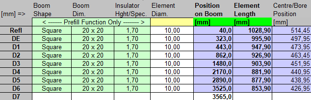
Geometry
 INSULATED THROUGH BOOM THIN ELEMENTS (BC acc. 6WU)
Pos. 1/2 Length BC 20 mm BC 20 mm BC 25 mm BC 1"
in NEC = 2.2 = 2.2 = 3.4 = 3.5
Refl. 0 514.5 1033.2 1031.2 1032.4 10xx.x
DE 283 496.0 994.2 994.2 995.4 9xx.x
D1 403 480.0 966.2 962.2 963.4 9xx.x
D2 822 471.0 949.2 944.2 945.4 9xx.x
D3 1440 460.5 927.2 923.2 924.4 9xx.x
D4 2130 450.0 907.2 902.2 903.4 8xx.x
D5 2850 448.5 905.2 899.2 900.4 8xx.x
D6 3485 433.5 875.2 869.2 870.4 8xx.x
ele.5 mm ele. 4 mm ele. 5 mm ele. 5 mm ele. 1/4"
Use WiMo made spare Folded Dipole for their YU7EF line EF0208c
or selfmade one with modified D1 as follows:
Note: for elements 4 mm D1 is of differing length for 5 and 8 ele. Yagi when using a folded DE
ele. 4 mm, Pos. 403 mm NEC => 480.5, 20x20 => 963.2, 25x25 => 964.4 mm, 1"x1"=> 96x.x
ele. 5 mm, Pos. 402 mm NEC => 481.0, 20x20 => 964.2, 25x25 => 965.4 mm, 1"x1"=> 96x.x
               INSULATED THROUGH BOOM THIN ELEMENTS (BC acc. 6WU)
        Pos.  1/2 Length   BC 20 mm    BC 20 mm   BC 25 mm    BC 1"
                 in NEC     = 2.2      = 2.2     = 3.4       = 3.5

Refl.     0      514.5     1033.2     1031.2      1032.4     10xx.x
DE      283      496.0      994.2      994.2       995.4      9xx.x
D1      403      480.0      966.2      962.2       963.4      9xx.x
D2      822      471.0      949.2      944.2       945.4      9xx.x
D3     1440      460.5      927.2      923.2       924.4      9xx.x
D4     2130      450.0      907.2      902.2       903.4      8xx.x
D5     2850      448.5      905.2      899.2       900.4      8xx.x
D6     3485      433.5      875.2      869.2       870.4      8xx.x
                ele.5 mm   ele. 4 mm  ele. 5  mm  ele. 5 mm  ele. 1/4"

Use WiMo made spare Folded Dipole for their YU7EF line EF0208c
or selfmade one with modified D1 as follows:
Note: for elements 4 mm D1 is of differing length for 5 and 8 ele. Yagi when using a folded DE
ele. 4 mm, Pos. 403 mm NEC =>  480.5, 20x20 => 963.2, 25x25 => 964.4 mm, 1"x1"=> 96x.x
ele. 5 mm, Pos. 402 mm NEC =>  481.0, 20x20 => 964.2, 25x25 => 965.4 mm, 1"x1"=> 96x.x


                    ON BOOM ELEMENTS (standard ins.)        SM7DTT ins.
        Pos.   1/2 Length  BC 20x20   BC 25x25   BC 1"x1"    BC 20x20
                 in NEC     = 3.9      = 7.6      = 7.9        = 3.0

Refl.     0      514.5     1032.9      1036.6     1034.9      1032.0
DE      283      496.0      995.9       999.6      999.9      990 Folded
D1      403      475.0      953.9       957.6      954.3       967.0
D2      822      466.0      935.9       939.6      935.9       945.0
D3     1440      454.5      912.9       916.6      912.9       924.0
D4     2130      443.0      889.9       893.6      889.9       903.0
D5     2850      439.0      881.9       885.6      881.9       900.0
D6     3485      423.8      851.5       855.2      851.5       870.0
                ele. 8 mm  ele. 8 mm  ele. 8 mm  ele. 3/8"  ele. 5 mm

Element lengths corrected 2013-03-26
Note: element lengths for Ø 8 mm fit 5/16" too

Use WiMo made Folded Dipole (spare from YU7EF line EF0208c)
or selfmade one with modified D1 as follows:
NEC => 477.0, 20x20 => 957.9, 25x25 => 961.6 mm, 1"x1"=> 961.9
Folded DE tip-to-tip = 990, inner height = 54, diam. = 10

- - - - - - - - - - - - - - - - - - - - - - - - - - - - - - - -
The Driver Dipoles diameter is 10 mm for all examples.
Use EZNEC's Auto-Segmentation at 144.1 MHz for RL and SWR plots
Use EZNEC's Auto-Segmentation at 350 MHz and correct elem. lengths
by -2.4 mm to produce radiation plots
ON BOOM ELEMENTS (standard ins.) SM7DTT ins.
Pos. 1/2 Length BC 20x20 BC 25x25 BC 1"x1" BC 20x20
in NEC = 3.9 = 7.6 = 7.9 = 3.0
Refl. 0 514.5 1032.9 1036.6 1034.9 1032.0
DE 283 496.0 995.9 999.6 999.9 990 Folded
D1 403 475.0 953.9 957.6 954.3 967.0
D2 822 466.0 935.9 939.6 935.9 945.0
D3 1440 454.5 912.9 916.6 912.9 924.0
D4 2130 443.0 889.9 893.6 889.9 903.0
D5 2850 439.0 881.9 885.6 881.9 900.0
D6 3485 423.8 851.5 855.2 851.5 870.0
ele. 8 mm ele. 8 mm ele. 8 mm ele. 3/8" ele. 5 mm
Element lengths corrected 2013-03-26
Note: element lengths for Ø 8 mm fit 5/16" too
Use WiMo made Folded Dipole (spare from YU7EF line EF0208c)
or selfmade one with modified D1 as follows:
NEC => 477.0, 20x20 => 957.9, 25x25 => 961.6 mm, 1"x1"=> 961.9
Folded DE tip-to-tip = 990, inner height = 54, diam. = 10
- - - - - - - - - - - - - - - - - - - - - - - - - - - - - - - -
The Driver Dipoles diameter is 10 mm for all examples.
Use EZNEC's Auto-Segmentation at 144.1 MHz for RL and SWR plots
Use EZNEC's Auto-Segmentation at 350 MHz and correct elem. lengths
by -2.4 mm to produce radiation plots
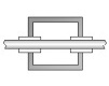
Sketch of Folded Dipole

This Yagi with 10 mm elements on a 20 x 20 mm boom with standard insulators
|
|
Ele. 10.0 mm
DE 10 mm
Boom 20 x 20 mm
|
"Ready to saw and drill" data for mounting elements on boom with BC according DG7YBN for standard insulators as sold by Konni, Nuxcom, WiMo, 7arrays:
Includes an SBC of 0.0 mm
Here is a very helpful overview on the stages of the YBN 5- 5 / 8 / 10 ele. project provided by Stef, F4EZJ
It shows what elements are shared and different at what positions on the boom for the various combinations
Note: Lengths given fit elements mounted on a 20 x 20 mm boom with 'standard insulators' and M3 screw


Sketch of Boom

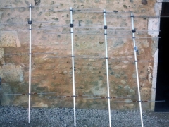
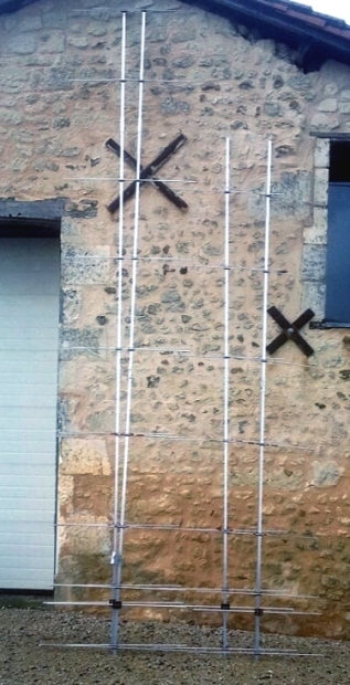
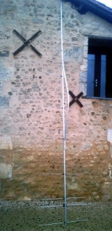
F4EZJ, Stef, building a 4 Yagi Bay of YBN 2-8
→ Place mouse over images to enlarge

|
|

|
|
Four YBN 2-5 basic Yagis lined up ...
|
|
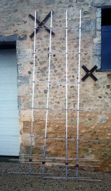
Four extended YBN 2-5 => YBN 2-8
|

|
|

|
Stef builds on 20 x 20 mm boom using 8 mm elements mounted semi-insulated
on boom with standard insulators and M3 screws
|
2 x YBN 2-8 and YBN 2-10
|
|
and YBN 2-10 with strut
|
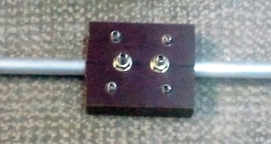
External link to Stef's 'Onedrive' online album with many detailed photos
which includes an ingenious way of producing a split dipoles center part.
Well done and thank you Stef!
Pattern and VSWR Plots
Elevation and Azimuth plot at 144.1 MHz


Return Loss and VSWR plot - Version with Folded Dipole from WiMo EF0208c

miniVNA: 144.30 MHz, Z = 50.2 Ohm, SWR = 1.07, RL = -29 dB

Note: this plot is taken on a build without any post tuning on DE or D1.
Just the "On-Boom-BC" added. Use additional Segmentation BC when starting
with the NEC models geometrie or simply take the geometry numbers given above.
YBN 2-8m xpol
Single YBN 2-8m xpol: note the modified elements in order to produce a clean and feasible build.
Total length of boom mechanically is 3865 mm which includes 40 mm ends offset at rear and front.
Boom cross section 25 x 25 x 2 mm or 1 x 1" and elements 8 mm are suitable.

EZNEC wires table: offset 24 mm for simulating 8 mm elements mounted on boom.
Offset between dipoles of h and v-plane is Position 283 mm to 583 mm = 300 mm

4 bay of YBN 2-8m xpol at 2.765 m vertical and horizontal stacking distance

3D View on structure using 4nec2

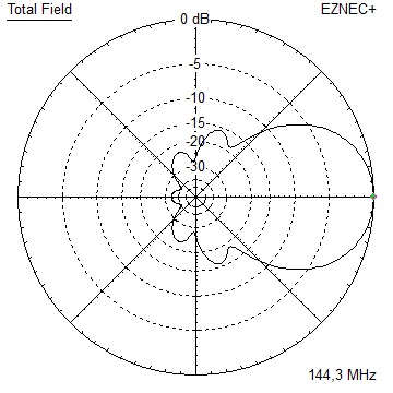
Azimuth Plot of h and v-plane radiating

Azimuth and Elevation Plot of v-plane
 
Antenna G/T with AGTC_lite by F5FOD with DG7YBN:
using vertical polarisation only this is -4.52 dB G/T and 19.1 dBi or 17.0 dBD of forward gain.
145.5 MHz FM Version
• with Folded Dipole

• This Yagi with 5 mm elements on a 20 x 20 mm boom with SM7DTT insulators or Stauff clamps

|
|
Ele. 5.0 mm
DE 10 mm
Boom 20 x 20 mm
|
"Ready to saw and drill" data for mounting elements on boom with BC according DG7YBN for higher insulators
such as SM7DTT holders and Stauff hydraulic clamps:

• This Yagi with 8 mm elements on a 20 x 20 mm boom with SM7DTT insulators or Stauff clamps
|
|
|
Ele. 8.0 mm
DE 10 mm
Boom 20 x 20 mm
|
"Ready to saw and drill" data for mounting elements on boom with BC according DG7YBN for higher insulators
such as SM7DTT holders and Stauff hydraulic clamps:

Note the D1 position and length are preliminary. These are subject to trimming
The Drivers diameter is 10 mm for all examples.
Use Folded Dipole with same dimensions as in sketch above.
The EZNEC model is done with Auto-Segmentation at 144 MHz
Elevation Plot 8 mm el.

Azimuth Plot with offset between folded dipole center and element plane = 22 mm

Return Loss and SWR plots - simulated

Downloads
EZNEC file of this Yagi with Straight Split DE

Read more about building this Yagi in my Article "5-8 ... an extendable 144 MHz Yagi" in Dubus 4/2012
Stacking
Stacking Dist.    DL6WU Formula
H-plane               2.59 m
E-plane               2.94 m
Data of 8 over 8 Yagi stack using DL6WU stacking distances

Gain vs. isotr. Rad.  16.0 dBi
Gain vs. Dipole       13.9 dBD
F/B                  -33.1 dB
F/R                  -24.8 dB
T_ant                237.7 K*
G/T                  -7.75 dB*
Theoretical numbers, no phasing line losses
nor imperfections caused by H-frame included
Data of 4 Yagi bay using DL6WU stacking distances

Elevation plot

Gain vs. isotr. Rad.  19.0 dBi
Gain vs. Dipole       16.9 dBD
F/B                  -34.6 dB
F/R                  -19.7 dB
T_ant                238.8 K*
G/T                  -4.79 dB*
Theoretical numbers, no phasing line losses
nor imperfections caused by H-frame included
*) T_sky = 200 K, T_earth = 1000 K as in VE7BQH G/T table
73, Hartmut, DG7YBN

|
|