-
• Main Page
- • Home
• Antennas - • 144 MHz
- Bent dipole GTV
144 MHz YagisGTV 2-7w: 2.7 m wide band width version of the low impedance, yet 50 ohms direct feed Low Noise Yagi with bent DE introduced in Dubus 1/2013
Elevation Plot

- YBN 3+7 SATA Satellite Yagi with 3 ele. for 145 MHz + 7 ele. for 435 MHz for handheld use
Elevation Plots
- YBN 2-2wA 50 ohms direct feed 2 ele. Yagi with high potential as broad beam Contest Stack.
See yourself and compare to DJ9HO Double Quads and 7ZB Oblongs. Full details on 2 and 4 Yagi stacks are given
3D Pattern of 4 x Stack

- YBN 2-5m (5-8)1.6 m high F/R, good willing 50 ohms direct feed Yagi as introduced with bent DE short version of the 5-8 in Dubus 4/2012
Elevation Plot
- YBN 2-6m 1.9 m long, good willing 50 ohms direct feed Yagi, related to the 5-8 project (same positions refl, dipole, D1, D2 ... same size folded dipole)
Elevation Plot

- YBN 2-7m 2.8 m high F/R, good willing 50 ohms direct feed Yagi, related to the 5-8 project (same positions refl, dipole, D1, D2 ... same size folded dipole)
Elevation Plot

- YBN 2-7mz 28 Ω2.8 m high F/R, good willing 28 ohms direct feed Yagi
Elevation Plot
- YBN 2-8m (5-8)3.6 m nice G/T, good willing 50 ohms direct feed Yagi as introduced with bent DE expanded version of the 5-8 in Dubus 4/2012
Actually it seems to be so good that DK7ZB decided to use it as draft for the 8 ele. OWM he just published.
Elevation Plot
- YBN 2-8mz 28 Ω3.6 m 25/28 ohms version of the YBN 2-8m
The stacked 25 ohms Yagi can easily be phased with 50 ohms coax cables
Elevation Plot

- YBN 2-9mz 28 Ω4.3 m high F/R, high G/Ta 28 ohms Yagi
Elevation Plot

- YBN 2-9m4.5 m moderate band width, low Antenna Temperature, good willing 50 ohms direct feed Yagi - a straigh DE version twin to the GTV 2-9m
Elevation Plot
- YBN 2-10w (5-8)5 m wide band, good willing 50 ohms direct feed Yagi as introduced with straight DE expanded version of the 5-8 in Dubus 4/2012
Elevation Plot
- YBN 2-10wz 12.5Ω5.1 m - 144.0 to 144.8 MHz wide band 12 ohms OWL-style Low Noise Yagi with straight DE and very low back lobes only
Elevation Plot

- YBN 2-12wz 12.5Ω6.8 m wide band 12 ohms OWL-style Low Noise Yagi with straight DE and very low back lobes only
Azimuth Plot:
- Bent dipole GTV
YBN 2-9m Yagi with Straight Dipole
EME + SSB modest bandwidth version ... strictly G/T breeding with a straight dipole
This Yagi is a twin to the GTV 2-9m designed for those who yield to avoid producing and trimming a bent dipole. With rearranged driver cell this Yagi's performance is only a fraction away from the GTV version by means of losing just a marginal bit on the backlobes: F/B and F/R are down by approximately 1.5 dB compared to the GTV 2-9m.
This medium length Yagi is balanced between gain and Antenna Temperature. However providing a modest bandwidth compared to its sister design, the GTV 2-9n. In comparison to most of the entries with exceptional G/T around 2.15 wl in the 144 MHz VE7BQH G/T table its T_ant is approximately 5 ... 10 K lower. Thus it may be very useful in difficult RXing scenarios like contests or EME from within a city with a small size 4-Yagi-Bay only. Design date of issue: 2019.02.22
Current Profile
Performance Data
Gain vs. isotr. Rad.  14.0 dBi
Gain vs. Dipole       11.8 dBD
-3 dB E-plane         38.4 deg.
-3 dB H-plane         42.8 deg.
F/B                  -26.5 dB
F/R                  -24.5 dB
Impedance               50 ohms
VSWR Band Width     1.24:1 *
Mechan. Length        4492 mm
Electr. Length        2.15 λ

Stacking Dist. h-pol.
top-to-bottom         2.85 m
side-by-side          3.16 m

*) as in VE7BQH G/T table = at 145.00 MHz
Geometry

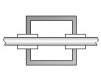
Table 1: YBN 2-9m, 4 mm elements through boom:
"Ready to saw and drill" data for mounting elements through boom with BC according SM5BSZ's BC.exe:
Note: with through Boom BC it is important to stick to the boom end offsets given below!
Metric Boom 20 x 20 x 2 mm
|
This table is only valid for: Boom shape: square Boom dim: 20 x 20 mm Wall thickn.: 2.0 mm Holes in boom: 6.0 mm Offset rear: 40 mm Offset front: 40 mm |
|

Note: with through Boom BC it is important to stick to the boom end offsets given below!
Note: This includes a "Segmentation Density Correction" (SBC) of 1.75 mm

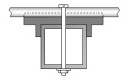
Table 2: YBN 2-9m, 8 mm elements on a 20 x 20 mm boom:
"Ready to saw and drill" data for mounting elements on boom with standard insulators. BC according DG7YBN:
|
Boom shape: square Boom dim: 20 x 20 mm |
|

Note: This includes a "Segmentation Density Correction" (SBC) of 1.75 mm

Table 3: YBN 2-9m, 8 mm elements on a 25 x 25 mm boom:
"Ready to saw and drill" data for mounting elements on boom with standard insulators. BC according DG7YBN:
|
Boom shape: square Boom dim: 25 x 25 mm |
|

Note: This includes a "Segmentation Density Correction" (SBC) of 1.75 mm

This design has been viewed how often after the first built has been published in Mar. 2019?
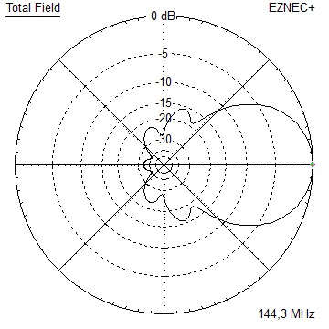
Pattern and VSWR Plots
Current distribution Elevation and Azimuth plot at 144.1 MHz


RL and SWR plot - simulated

Downloads
EZNEC file of this Yagi with 8 mm elem.
Stacking

Stacking Dist.    DL6WU Formula
H-plane               2.851 m =  9.353 ft
E-plane               3.163 m = 10.377 ft

X-pol Stacking Dist.
3.01 m each plane
Elevation and azimuth plot and data of 4 Yagi bay using DL6WU stacking distances


Gain vs. isotr. Rad.  19.8 dBi
Gain vs. Dipole       17.7 dBD
-3 dB H-plane         17.2 deg.
-3 dB E-plane         19.4 deg.
F/B                  -29.3 dB
F/R                  -26.4 dB
T_los                  4.4 K
T_ant                470.5 K*
G/T                  -6.89 dB*
Theoretical numbers, no phasing line losses
nor imperfections caused by H-frame included
*) T_sky = 290 K, T_earth = 5100 K as in VE7BQH G/T table using ITU-R temps.
73, Hartmut, DG7YBN