-
• Main Page
- • Home
• Antennas - • 144 MHz
- Bent dipole GTV
144 MHz YagisGTV 2-7w: 2.7 m wide band width version of the low impedance, yet 50 ohms direct feed Low Noise Yagi with bent DE introduced in Dubus 1/2013
Elevation Plot

- YBN 3+7 SATA Satellite Yagi with 3 ele. for 145 MHz + 7 ele. for 435 MHz for handheld use
Elevation Plots
- YBN 2-2wA 50 ohms direct feed 2 ele. Yagi with high potential as broad beam Contest Stack.
See yourself and compare to DJ9HO Double Quads and 7ZB Oblongs. Full details on 2 and 4 Yagi stacks are given
3D Pattern of 4 x Stack

- YBN 2-5m (5-8)1.6 m high F/R, good willing 50 ohms direct feed Yagi as introduced with bent DE short version of the 5-8 in Dubus 4/2012
Elevation Plot
- YBN 2-6m 1.9 m long, good willing 50 ohms direct feed Yagi, related to the 5-8 project (same positions refl, dipole, D1, D2 ... same size folded dipole)
Elevation Plot

- YBN 2-7m 2.8 m high F/R, good willing 50 ohms direct feed Yagi, related to the 5-8 project (same positions refl, dipole, D1, D2 ... same size folded dipole)
Elevation Plot

- YBN 2-7mz 28 Ω2.8 m high F/R, good willing 28 ohms direct feed Yagi
Elevation Plot
- YBN 2-8m (5-8)3.6 m nice G/T, good willing 50 ohms direct feed Yagi as introduced with bent DE expanded version of the 5-8 in Dubus 4/2012
Actually it seems to be so good that DK7ZB decided to use it as draft for the 8 ele. OWM he just published.
Elevation Plot
- YBN 2-8mz 28 Ω3.6 m 25/28 ohms version of the YBN 2-8m
The stacked 25 ohms Yagi can easily be phased with 50 ohms coax cables
Elevation Plot

- YBN 2-9mz 28 Ω4.3 m high F/R, high G/Ta 28 ohms Yagi
Elevation Plot

- YBN 2-9m4.5 m moderate band width, low Antenna Temperature, good willing 50 ohms direct feed Yagi - a straigh DE version twin to the GTV 2-9m
Elevation Plot
- YBN 2-10w (5-8)5 m wide band, good willing 50 ohms direct feed Yagi as introduced with straight DE expanded version of the 5-8 in Dubus 4/2012
Elevation Plot
- YBN 2-10wz 12.5Ω5.1 m - 144.0 to 144.8 MHz wide band 12 ohms OWL-style Low Noise Yagi with straight DE and very low back lobes only
Elevation Plot

- YBN 2-12wz 12.5Ω6.8 m wide band 12 ohms OWL-style Low Noise Yagi with straight DE and very low back lobes only
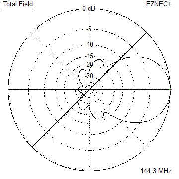
Azimuth Plot:
- Bent dipole GTV
YBN 2-8mz 28 / 25 Ω Yagi with straight Driven Element
Another variation of the well tested 5-8 series. Focussing on relatively good F/B with gain here is one more specimen. However for this 28 respectively 25 ohms versions many similarities except the origin come to an end. While the 18 ohm version offers a little bit higher gain and bandwidth the 25 ohms version enables us to phase 2 or 4 Yagis more easily with stubs of common 50 ohms coax cable.
These stubs must be odd multiples of 1/4 wl (mind the exact velocity factor at 144 MHz!) like 3/4, 5/4, 7/4 wl ... . For a vertical stack of two of these YBN 2-8mz 25 ohms a length of 7/4 wl per Yagi enables connecting the two at the half way point. As an example uisng Ultraflex 7 with a v-factorof 0.83 this equals 3016 mm including rf connectors.
Design date of issue: 2020.11.16

YBN 2-8mz 3D pattern plot at 144,1 MHz
Performance Data
Specs: with 8 mm elements @ 144.1 MHz
Gain vs. isotr. Rad.  13.1 dBi
Gain vs. Dipole       11.0 dBD
-3 dB E-plane         41.4 deg.
-3 dB H-plane         47.2 deg.
F/B                  -28.5 dB
F/R                  -22.2 dB
Impedance             28 / 25 ohms
VSWR Band Width       1.39:1 *
Mechan. Length        3485 mm plus 2 x 40 mm offset
Electr. Length        1.68 λ

Stacking Dist. h-pol. (144.1 MHz)
top-to-bottom         2.60 m or 8.5 ft
side-by-side          2.94 m or 9.7 ft

*) as in VE7BQH G/T table = at 145.00 MHz
How many VHF operators have been looking up this design since Nov. 2020?

Geometry
This Yagi with 8 mm elements on a 20 x 20 mm boom with standard insulators
|
Ele. 8.0 mm DE 10 mm Boom 20 x 20 mm |
|

"Ready to saw and drill" data for mounting elements on boom with BC according DG7YBN for standard insulators
as sold by WiMo, Tino's Funkshop, HF-Kits NL, 7arrays:

25 ohms version

The Drivers diameter is 10 mm for all examples.
The EZNEC model is done with Auto-Segmentation at 380 MHz
Pattern and VSWR Plots
Elevation and Azimuth plot at 144.1 MHz

Return Loss and SWR plots - simulated
Elevation plot at 144.1 MHz - 25 ohms version

more or less identical .....
Downloads
None so far.
Stacking
Stacking Dist.    DL6WU Formula (144.1 MHz)
E-plane               2.943 m
H-plane               2.598 m
Plot and data of 2 vertically stacked YBN YBN 2-8mz using DL6WU stacking distances
Antenna View & Elevation Pattern
Plot and data of 3 vertically stacked YBN YBN 2-8mz using DL6WU stacking distances
Antenna View & Elevation Pattern
Same with lowest Yagi at 4 m agl, perfect groungd assumed

Plot and data of 3 vertically STAGGER stacked YBN 2-8mz using DL6WU stacking distances, 504mm shift
Lowest Yagi 4.0 m agl, highest Yagi 9.2 m agl.
Plot and data of 4 vertically stacked YBN YBN 2-8mz using DL6WU stacking distances
Antenna View & Elevation Pattern

4 x vert. stack with lowest Yagi 4.0 m abover 'Perfect Ground'
F/B approx. -34 dB
Plot and data of 4 vertically STAGGER stacked YBN YBN 2-8mz using DL6WU stacking distances, 504mm shift
Lowest Yagi 4.0 m agl, highest Yagi 11.1 m agl.
19.1 dBi or > 16.9 dBd at close to 42 deg. HPBW in Azimuth with > -35 dB of F/B.
Elevation Pattern
4 x vert. stagger phased stack with lowest Yagi 4.0 m abover 'Perfect Ground'
F/B better -45 dB

Plot and data of classical H-shape bay of YBN 2-8mz using DL6WU stacking distances
Antenna View & Elevation Pattern


73, Hartmut, DG7YBN