-
• Main Page
- • Home
• Antennas - • Radio Sonde
- YBN RS 8wzA 1.3 m 8 element high performance 403 MHz 28 ohms Yagi for tracking Radio Sondes with clean pattern and comfortable bandwidth
This design is easy to reproduce in any way, with straight split dipole and feed with 2 x 75 ohms coax DK7ZB match
Elev. Plot

- YBN RS 14wA 3.1 m 14 element high performance 403 MHz Long Yagi for tracking Radio Sondes with clean pattern and comfortable bandwidth
This design is easy to reproduce in any way, with straight split dipole and direct feed with 50 ohms coax
3D Plot
- GTV RS 19mA 4.5 m 19 element high performance 403 MHz Long Yagi for tracking Radio Sondes with bent Driver, clean pattern and comfortable bandwidth
This design needs care when building a large enough calliper gauge for measuring element length is needed here for optimium perfomance.
Elev. Plot
- YBN RS 8wz
- • 28 MHz
- • 50 MHz
- • 70 MHz
- • 144 MHz
- • 432 MHz
GTV RS-19m Yagi with bent DE for reception of Radio Sondes
This Yagi is designed to give Radio Sonde Hunters a very clean pattern, high performance Long Yagi with the necessary
bandwidth for monitoring the 402 - 404 MHz core part of the Radio Sonde band. It is 50 ohms direct feed, the coax cable
can be connected as is. A ferrite core added on the fed line is welcome but not essential.
This design is derived using the GTV 70-19m 432 MHz Low Noise Yagi as baseline.
Now with full building plan (Download Area) including the 'Blade DE' as introduced in Dubus 4/2014
Current distribution
|
|
Performance Data
                       402 MHz        403 MHz       404 MHZ
Gain vs. isotr. Rad.  17.8 dBi       17.8 dBi      17.8 dBi
Gain vs. Dipole       15.5 dBD       15.6 dBD      15.6 dBD
-3 dB E-plane                        25.0 deg.
-3 dB H-plane                        26.0 deg.
F/B                  -34.6 dB       -30.9 dB      -28.1 dB
F/R                  -29.1 dB       -29.1 dB      -28.1 dB
Impedance                              50 ohms
Mechan. Length                       4413 mm
Electr. Length                       5.93 λ

Stacking Dist. h-pol.
top-to-bottom                        1.65 m or 5.4 ft
side-by-side                         1.72 m or 5.6 ft
Geometry
Element Diameter = 1/4 in = 6.35 mm, DE = 3/8 in = 9.525 mm (Update: 8 mm ele., see down the page)
Applying the SBC factor of 1.02 mm/MHz tells us that the SBC to be added to the BC must be
(404.7 - 403.2) MHz x 1.02 mm/MHz = 1.53 mm
Boom Correction for mounting elements on boom with standard plastic insulators
Segmentation BC and Base BC (see below) must be added.
Remember - this is UHF. Cut elements very precisely. Use a large calliper gauge if you can get one. Make a mark
for final length, saw about 0,5 mm in front of the mark and grind down to final measure. Below you find BC numbers for
other boom dimension
Data for 1/4" = 6.35mm elements:

             Tube dim.          BC            SBC          BC+SBC
Boom        20 x 20 mm        7.1 mm    +   1.53 mm   =    8.63 mm
Boom        25 x 25 mm       10.4 mm    +   1.53 mm   =   11.93 mm
Boom         1 x 1  in       10.7 mm    +   1.53 mm   =   12.23 mm
Elements on-boom-with-standard-insualators cutting table (corr. 2014.11.27)
Pos. Full Length Full Length | Pos. Full Length Full Length Full Length
in NEC on 20x20 Boom | in NEC on 20x20 Boom on 25x25 Boom
(7.1 + 1.5 mm) | (7.1 + 1.4 mm) (10.4 + 1.4 mm)
Refl. 0.0 356.5 365.1 | 0.0 355.0 363.5 366.8
DE(b) 97.0 97-343.0 351.6 | 97.0 96.5-342.0 350.5 353.8
DE(a) 112.0 0-97 96.0 | 112.0 0-96.5 95.5 95.5
D1 163.5 336.0 344.6 | 164.0 332.5 341.0 344.3
D2 264.0 330.5 339.1 | 264.0 327.0� 335.5 336.8
D3 459.0 319.0 327.6 | 459.0 314.5 323.0 326.3
D4 687.5 312.5 321.1 | 687.5 308.3 316.8 320.1
D5 952.0 308.0 316.6 | 952.0 304.0 312.5 315.8
D6 1235.0 306.0 314.6 | 1235.0 301.0 309.5 312.8
D7 1528.5 302.0 310.6 | 1528.5 296.3 304.8 308.1
D8 1830.5 296.0 304.6 | 1830.0 292.0 300.5 303.8
D9 2136.0 295.0 303.6 | 2136.0 290.0 298.5 301.8
D10 2434.5 294.0 302.6 | 2434.5 287.5 296.0 299.3
D11 2729.0 292.0 300.6 | 2728.5 286.5 295.0 298.3
D12 3021.5 291.0 299.6 | 3021.5 285.5 294.0 297.3
D13 3302.5 290.0 298.6 | 3302.5 283.0 291.5 294.8
D14 3585.5 288.5 297.1 | 3585.5 283.0 291.5 294.8
D15 3868.5 286.5 295.1 | 3868.5 279.0 287.5 290.8
D16 4163.5 282.0 290.6 | 4163.5 276.5 285.0 288.3
D17 4413.0 280.0 288.6 | 4413.0 272.5 281.0 284.3
ele. 1/4" ele. 1/4" ele. 1/4" | ele. 8mm ele. 8 mm ele. 8 mm ele. 8 mm
(*) Note: element lengths for Ø 8 mm fit 5/16" too
The Drivers diameter is 3/8" for 1/4" elem. and 10 mm for 8 mm elem. design.
Use EZNEC's Auto-Segmentation at 1050 MHz.
SBC 8 mm model: the 8 mm models f_res at given high segmentation is 403.1 MHz.
At conservative auto segmentation on 403 MHz it lands in at 404.5 MHz
Delta is 1.4 MHz with a factor of 1.02 mm/MHz this results in 1.448 extra mm.
Element through boom - with numbers derived using SM5BSZ's BC.exe applied
Ready to saw and drill" data for mounting elements on boom with standard insulators on 20 x 20 mm boom including a 30 mm offset from boom ends:
Insulators Ø_outer = 6 mm, Ø_inner = 4 mm press fit, booms wall thickness = 2 mm
SBC 4 mm: (404.3 MHz - 403.1 MHz) x 1.02 mm/MHz = 1.224 mm plus 0.7 mm on top to compensate insulators influence
makes a total of 1.224 + 0.7 mm = 1.924 mm
The Drivers diameter is 10 mm for the 4 mm elem. design.
Use EZNEC's Auto-Segmentation at 1050 MHz.
Find a technical drawing of this Yagis boom and strut in the Download section
Advanced feeding & symmetrising
Placing a ferrite an the feeding coax as close a possible to the dipole connection will do for any reception purpose
However - here is an advanced methode:
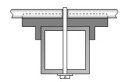
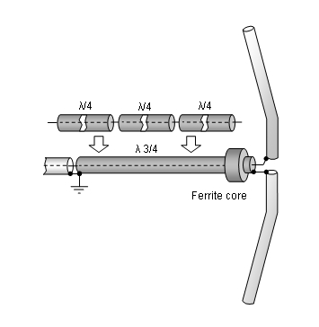
A simple symmetrising member may be made from a 3 x 1/4 Lambda line grounded at the far side with
N-flange-bushing and an aluminium plate and ferrite added as close as possible to the DE, see below.
Pattern and VSWR Plots
Elevation and Azimuth plot at 432.1 MHz (horizontally polarised - for vertical polarisation swap views)

SWR plots - inner band and full band

How came to visit this website?
Downloads - file update 2014-11-29
EZNEC file of this Yagi with 4 mm elements
EZNEC file of this Yagi with 1/4" elements
EZNEC file of this Yagi with 8 mm elements
Drawing of boom of this Yagi in 2 sections

Drawing of boom of this Yagi in 3 sections
Drawing of this Yagis 'Blade' Dipole in 2 mm aluminium sheet metal
Mounting a long vertically polarised Yagi
one. With help of a traverse and V-shaped kevlar, aramid or polyester guy ropes one can avoid boom sag
and add additional stability as now the supporting structure becomes 3 dimensional.
Place strut ends and guy rope fastenings as far away from elements as possible.
Bill of Materials
On-Boom-Builds
Element mounts
18 pcs: insulator 25 mm square boom (WiMo #23042.25)
18 pcs: stainless screw M3 x 40 for 25 mm boom (or 45) mm
18 pcs: M3 washers, large (Ø 9.1 mm)
18 pcs: M3 washers, ordinary (Ø 7 mm)
18 pcs: M3 self locking nut
Quarter Wave Line
1 pc: RG - 142 B/U, 400 mm (trimm to resonate at 403 MHz as 3 x 1/4 λ, approx. 373 mm)
1 pc: N-cable-flange-bushing
Boom Connnector
1 (2) pcs: Boom connector 25x25 mm boom (WiMo #23033)
2 (4) pcs: screw M6 x 35
2 (4) pcs: nut M6
4 (8) pcs: M6 washer
Other
6 pcs: Screw M3 x 8
4 pcs: M3 washers, ordinary (Ø 7 mm)
4 pcs: M3 nuts
... will be continued
Stacking
For Stacking Pattern Data and Plots on the GTV RS-19m => see GTV 70-19m
Symmetrising 50 to 50 ohms Feedline
The principle is similar to the 1/4 Lambda coax. Adding 2 x 1/4 Lambda or a half wave line does not change anything but allows
to form a gentle bow below the boom or until behind the Reflector. Follow practical construction hints on "Building a Yagi" page.

|
Attenzione!
Take care when lengthening the coax, measure the right length instead of refering to given v-factors only. A good choice may be the diam. 5 mm PTFE coax RG-142 B/U: real resonate length (403 Mhz as 3/4 Lambda) shield-shield is around 373 mm. |

|
Find more information
about getting the coax stub right on my Phasing & Matching Lines page |
73, Hartmut, DG7YBN