-
• Main Page
- • Home
• Antennas - • Radio Sonde
- YBN RS 8wzA 1.3 m 8 element high performance 403 MHz 28 ohms Yagi for tracking Radio Sondes with clean pattern and comfortable bandwidth
This design is easy to reproduce in any way, with straight split dipole and feed with 2 x 75 ohms coax DK7ZB match
Elev. Plot

- YBN RS 14wA 3.1 m 14 element high performance 403 MHz Long Yagi for tracking Radio Sondes with clean pattern and comfortable bandwidth
This design is easy to reproduce in any way, with straight split dipole and direct feed with 50 ohms coax
3D Plot
- GTV RS 19mA 4.5 m 19 element high performance 403 MHz Long Yagi for tracking Radio Sondes with bent Driver, clean pattern and comfortable bandwidth
This design needs care when building a large enough calliper gauge for measuring element length is needed here for optimium perfomance.
Elev. Plot
- YBN RS 8wz
- • 28 MHz
- • 50 MHz
- • 70 MHz
- • 144 MHz
- • 432 MHz
YBN RS-14w wideband Yagi for reception of Radio Sondes
Wideband version with SWR < 1:1.5 from 400 to 406 MHz
This Yagi is designed to meet expectations for easy building but clean pattern for the necessary bandwidth for monitoring
the complete 400 - 406 MHz Radio Sonde band. It is 50 ohms direct feed, the coax cable can be connected as is.
A ferrite core added on the fed line is welcome but not essential.
This design is developed using the GTV 70-14m 432 MHz Low Noise Yagi as baseline.
Current distribution

This far the YBN RS-14w has been built by Daniel, OM1ATS and Yves, F5RBP.
Daniel states "In first test antenna has very good SWR near 403 MHz".
Yves closely followed the given geometry of the wave guiding structure and
yields SWR in place too. He even modified the designs driver cell to fit a bent
Dipole on his own.
• see here for Plot and Photos of F5RBP's Yagi
Performance Data
                       402 MHz        403 MHz       404 MHZ
Gain vs. isotr. Rad.  16.1 dBi       16.1 dBi      16.2 dBi
Gain vs. Dipole       14.0 dBD       14.0 dBD      14.1 dBD
-3 dB E-plane                        31.2 deg.
-3 dB H-plane                        33.0 deg.
F/B                  -31.2 dB       -28.9 dB      -26.9 dB
F/R                  -25.8 dB       -25.3 dB      -24.3 dB
Impedance                              50 ohms
Mechan. Length                       3031 mm
Electr. Length                       4.07 λ

Stacking Dist. h-pol.
top-to-bottom                        1.31 m
side-by-side                         1.38 m
Geometry
Applying the SBC factor of 1.02 mm/MHz tells us that the SBC to be added to the BC must be
(405.5 - 403.6) MHz x 1.02 mm/MHz = 1.94 mm
(corrected using right SBC factor for 403 MHz instead the 432 MHz number / 2014-07-10)
Boom Correction for mounting elements on boom with standard plastic insulators
The 8 mm element geometry data are to fit On-Boom-with-Standard-Insulators style (WiMo, Nuxcom, ...) of building.
Segmentation BC and Base BC (see below) must be added.
for final length, saw about 0,5 mm in front of the mark and grind down to final measure. Below you find BC numbers for
other boom dimension
             Tube dim.          BC            SBC          BC+SBC
Boom        20 x 20 mm        7.1 mm    +   1.94 mm   =    9.04 mm
Boom        25 x 25 mm       10.4 mm    +   1.94 mm   =   12.34 mm
Boom         1 x 1  in       10.7 mm    +   1.94 mm   =   12.64 mm
Elements through boom
For building with elements through boom see DL6WU/G3SEK Boom Correction Online Calculator
Do not miss out on adding the 1.94 mm of SBC.
Advanced feeding & symmetrising
Placing a ferrite an the feeding coax as close a possible to the dipole connection will do for any reception purpose
However - here is an advanced methode:
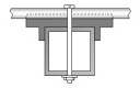
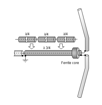
A simple symmetrising member may be made from a 3 x 1/4 Lambda line grounded at the far side with
N-flange-bushing and an aluminium plate and ferrite added as close as possible to the DE, see below.
Pattern and VSWR Plots
Elevation and Azimuth plot at 432.1 MHz (horizontally polarised - for vertical polarisation swap views)


SWR plots - inner band and full band

How came to visit this website?
Downloads
EZNEC file of this Yagi with 8 mm elements
Mounting a long vertically polarised Yagi
one. With help of a traverse and V-shaped kevlar, aramid or polyester guy ropes one can avoid boom sag
and add additional stability as now the supporting structure becomes 3 dimensional.
Place strut ends and guy rope fastenings as far away from elements as possible.
Stacking
Stacking Dist.    DL6WU Formula
v-pol               1.31 m
Data of 2 Yagi stack using DL6WU stacking distances

Gain vs. isotr. Rad.  19.0 dBi
Gain vs. Dipole       16.8 dBD
F/B                  -28.5 dB
F/R                  -26.4 dB

Theoretical numbers, no phasing line losses
nor imperfections caused by H-frame included
*) T_sky = 200 K, T_earth = 1000 K as in VE7BQH G/T table
Azimuth Plot of 2 x vertical polarised YBN RS-14w
(Elevation Plot is same as Az. Plot given for single Yagi in h-pol above)
Symmetrising 50 to 50 ohms Feedline
The principle is similar to the 1/4 Lambda coax. Adding 2 x 1/4 Lambda or a half wave line does not change anything but allows
to form a gentle bow below the boom or until behind the Reflector. Follow practical construction hints on "Building a Yagi" page.

|
Attenzione!
Take care when lengthening the coax, measure the right length instead of refering to given v-factors only. A good choice may be the diam. 5 mm PTFE coax RG-142 B/U: real resonate length (403 Mhz as 3/4 Lambda) shield-shield is around 373 mm |

|
Find more information
about getting the coax stub right on my Phasing & Matching Lines page |
73, Hartmut, DG7YBN