|
....... |
Boom Struts
 Split Struts Split Struts
Planning a Strut
Storm Suspension
Mounting a long vertically polarised Yagi
How to bend properly with selfmade tools
A simple wooden bending dye
Simple Steel Dye
Semi-Professional Dye / Jig
UHF Yagis
How to stay clear of the mast on UHF
Boom Joints
Self made Boom Joints 25x25 mm
|

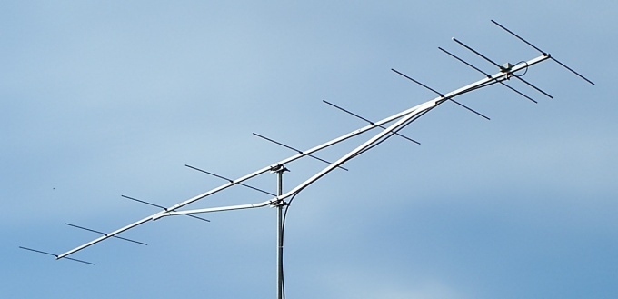
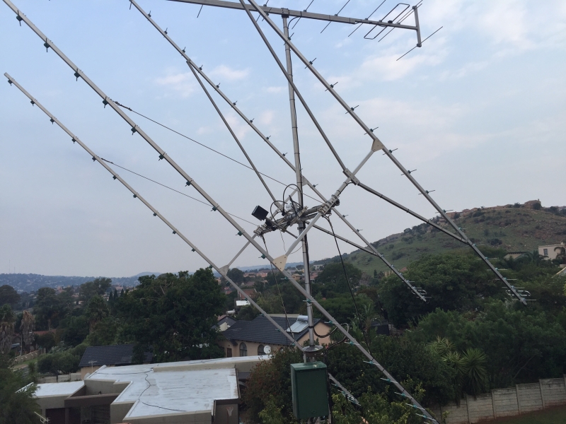
G0KSC's InnovAntennas makes use of my strut layout scheme en regular as you can see on this impressive stack of LFA-Q Yagis
|
Want to produce a sound boom strut that not only looks orderly but grants maximum efficiency for boom reinforcement for the amount of tubing put in?
Then why not follow leading professionals - At InnovAntennas Limited they build struts according the scheme I show below for good reasons. And isn't that
24 ele. LFA a beauty not only by the very effectivly noise cancelling rear pattern but by mechanical design too?
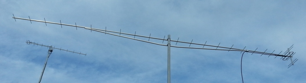
Photo on courtesy of Justin Johnson - G0KSC, InnovAntennas
"This 24el 432Mhz LFA has been optimised for weak signal work including EME. This antenna is 20' long and yet weighs in at just 10Lbs including all fixing hardware."
How to get there
Build your boom, add elements, DE and coax. Then find the balance point and mark it with tape.
Now measure a good length that fits a supports needs either end. One that does not interfere with element mounting positions.
The ideal positions would be half way between elements. You might have shift the balance point by a few inches for that.

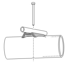
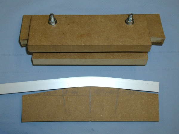
The challenge is to get the bending angles to have even fastening ends to the boom. So that both ends are in parallel to the boom.
This I do by making the two pieces of the strut of idential length and shape per each end. Now one only has to bend all 4 ends same
way which is reproducible if we use a simple bending dye.
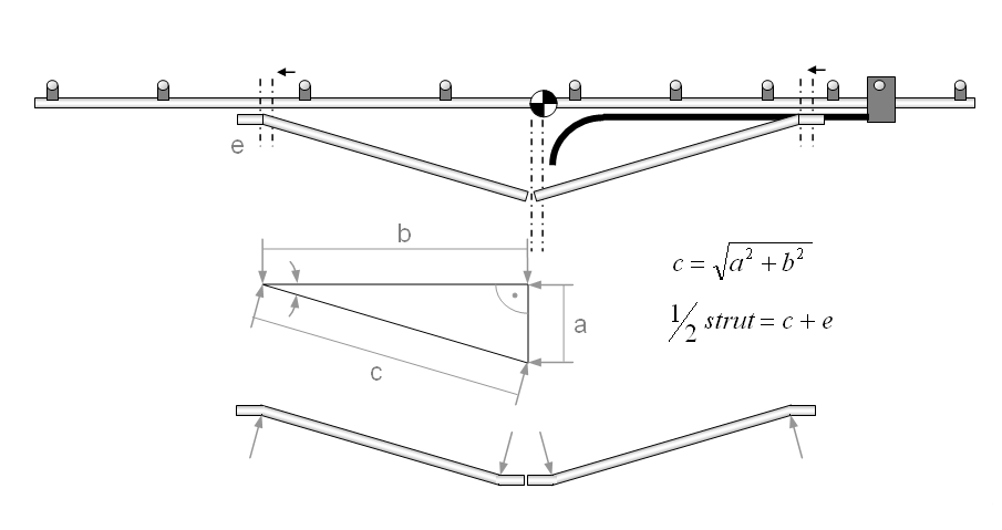
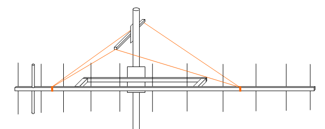
Determinating the 1/2 strut straight materials cutting length: Draw a sketch with a triangle, angles 15 ... 30 degr. approx. between
boom an strut pieces. Calculate the strut piece lengths and add like 70 mm for fastening it to the boom.
Once you have bent a few tubes and have extended your expertise you might try to do single boom struts by taking the double length,
marking the center and bent both sides. How to get both sides even? Either use a professional bending tool with ridgid aiming position
or bent to about 95%, of wanted angle, hold against a straight beam and adjust in steady steps.
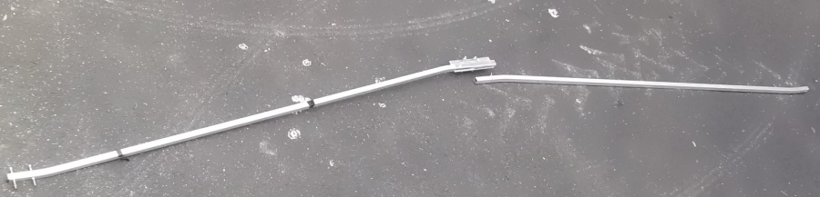
Boom Struts to pieces ?
Boom joints can be done in two or three pieces if the joints are stiff enough.
Below: 1 x Split Boom strut for the 6.7 m long GTV 2-12 (20 x 20 mm)
Below: 2 x Split Boom strut with a length of 5.04 m for the 8.2 m long GTV 2-14 (25 x 25 mm), a 1 m scale is enclosed.
I use 2 of the shown above heavy duty joints on this.

Below: 1 x Split Boom Strut with a length of 2.9 m underneath the 5.2 m EF0210LT
Below: Unsplit Boom Strut underneath a 4.1 m 70 cm EF7017. This is bent as one piece.
Actually it should be a bit longer, not to spoil the BC by getting close to any mounted element (!)

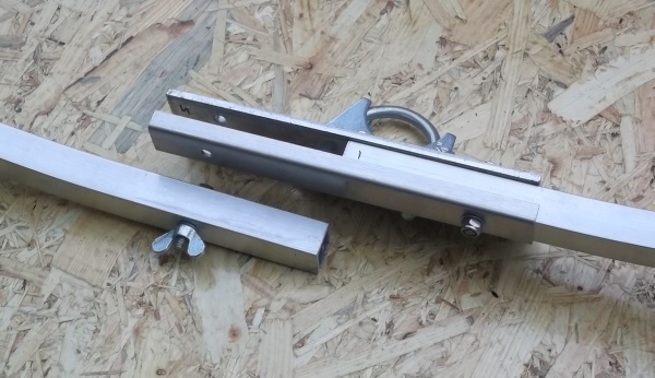
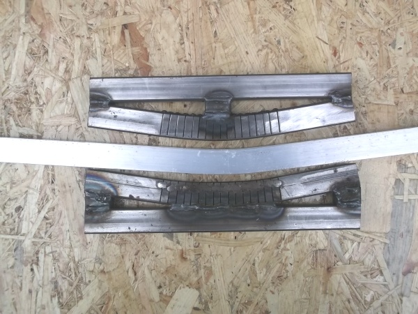
Below: Mid joining section of the 20 x 20 mm GTV 2-12 strut. Note the reinforcing plate
opposite side of the mast mount. That and the solid plate enclose the struts profile either
side to give max. strength.
This is pretty much the way 'Antennes Tonna, France' make their struts and strut joints for their well known 432 Mhz 21 ele. Yagi
All of my 1 x split struts joints are done this way. I have two of the shown EF0210LT up myself
since three years now with non lost (hi).

Planning a Strut
Nice Yagi, .. just a bit fragile boom

Nicer with sound strut
The shown strut employs two identical aluminium bars. Dim. 20 x 20 x 1 or 20 x 20 x 2.
Both are bend in identical way on same dye on both sides. That way they are symmetrical in lengths and angles.

Storm Suspension
How to add stability to long Yagis booms so they can stand the weather in exposed spots

Long Yagis tend to swing and vibrate in gale winds. Because the free boom ends can be pushed either side
by the force of the wind. Adding stability by increasing the booms cross sectional diameter is one way
of dealing with this issue.
However a far more effective methode is to add a dimensional stabilty
if possible the way the antenna is mounted. A 'triangulated' rope suspension adds a left / right dimension to the
thin boom tube. Which because of its dimension can potentially add way more strength to the boom & strut construction
than say doubling the booms thickness can.
• Use quality ropes or guy wires that provide little to nill lengthening.
Sailing shops hold very good wire ropes with Kevlar, Dyneema (R), aramid or polyester guy rope or other cores
that provide strength and lenghtening close to steel wires at thin diameters.
• An important detail is how to attach wires at far boom ends; do not drill large holes through the boom
here. Or fit reinforcenment plates if you do so. We do not want to weaken the boom tube locally,
especially not at a point where we lead forces into it.
• Fixing points shall be far way from element positions to ensure least influence on the electrical properties
of the Yagi-Uda. That typically is in the mid point between two elements.
• Find a photo of an example here with the almost 7 m long 144 MHz UR5EAZ 12 ele. build on a plastic lace of 24 x 28 mm as boom
Mounting a long vertically polarised Yagi
An ordinary boom strut may be used to produce a fixed distance to the pole. Which ideally should be a fiberglass
one. With help of a traverse and V-shaped kevlar, aramid or polyester guy ropes one can avoid boom sag
and add additional stability as now the supporting structure becomes 3 dimensional.
Place strut ends and guy rope fastenings as far away from elements as possible.
H-Frame for a 4bay of vertical polarised Yagis

Photo and built by ZS6JOn, tnx John!
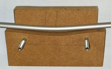
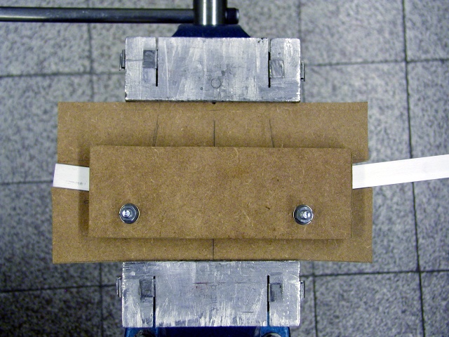
A simple dye made from hard wood

When making the dye
 	• Do not apply bending angles in excess of some 15 degrees.
	  Hardened aluminum might not take more bending without problems.

	• Apply 1 ... 2 degrees more since the bended metal will spring back
	  when pressure is released.

 	• Make ends run out flat for at least some 70 mm.
	  These give guidance and may serve a fixing areas later on.
	  Use outer edge as mark for inserting the square rods edge to edge.
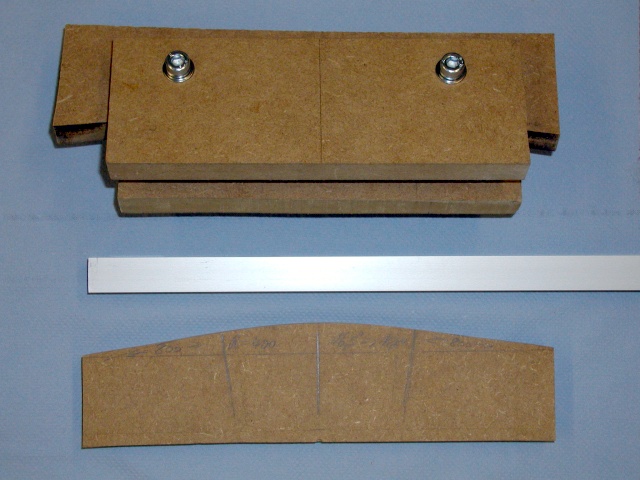
Applying some pressure ... use a large vice.

Press until you feel a sudden increase in resistance

| ... note the spring back
|

| make a test on a coarsly made dye and add that angle before producing your real strut
|
Steel Dye for tougher tasks
While the wooden dyes are feasible for 15 x 15 and 20 x 20 mm material for
any stronger lile 25 x 25 it takes a stronger dye. This one is welded from
mild steel:
Attenzione!
Stronger material ... more springback. Note the difference in bending angle of
dye and aluminium.
Attenzione!
A mild steel in heavy contact with aluminium will quite likely harm the passivation
layer of the aluminium. It would be ideal to use a plastic inlay or stainless or whatever
is hard enough and does not corrode.
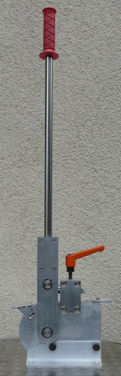
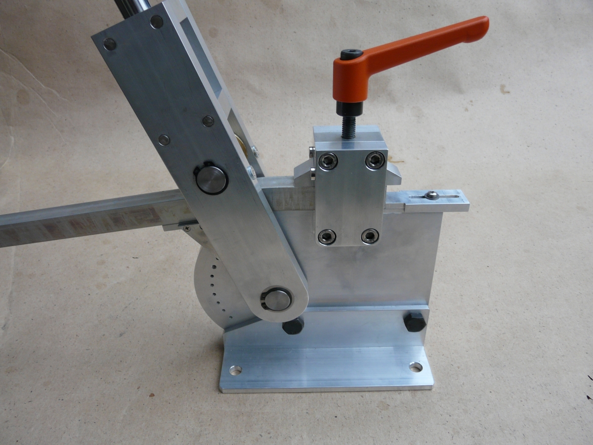
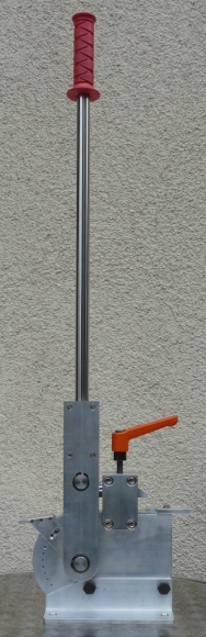
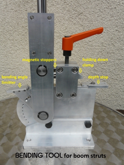
Semi Professional Dye
However, a bending tool for commercial demands would never have a static matrize side.
One could use heavy duty rolls for this (like the RS Componets # 459-0169, see "RS online")

For easy reproduction it is essential to have a back square on one side.
And a well designed and built Bending Dye by Jörg, DL2VL
A brief description:
- Max. tube cross section 20 x 20 mm
- Depth stopper for reproducible measures
- Adjustable delimitation of bending angle from 0 up to 90°, R = 70 mm
- Stable downholder for firm clamping of the tube
- Magnetic fixture of the lever in home psition
- Shaft bearing in sinter bushings
Deutsche Beschreibung s. unterhalb der Fotos.
Fotos and Build: On Courtesy of DL2VL. Tnx Jörg!
Click on images to enlarge.


Kurze Beschreibung:
- max. Rohrquerschnitt 20 x 20 mm
- Tiefenanschlag für reproduzierbare Maße
- Einstellbare Biegewinkelbegrenzung von 0 bis 90°, R = 70 mm
- stabiler Niederhalter für feste Klemmung des Rohres
- magnetische Fixierung des Hebelarms in der Nulllage
- Wellenlagerung in Sinterbuchsen
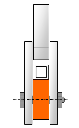
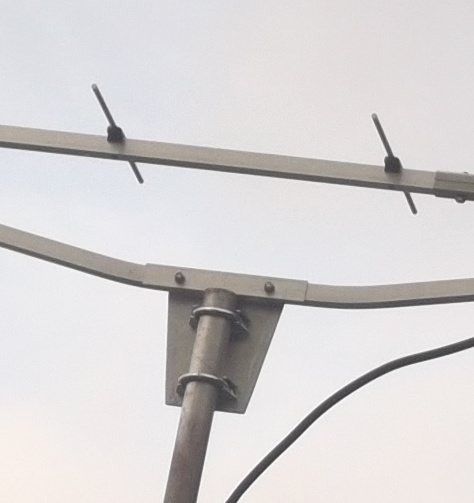
How to stay clear of the mast on 432 MHz and above
Attenzione!
The influence of a pole sticking right thru your UHF Yagi including mounting clamp and all is a serious one.
Especially when the mast is not in ´symmetry with the element centres, as must be when attached sideways to the pole tube.
As imperfect as a simulated boom tube may be in any NEC program. The outcome shows plenty of pattern deterioration, the more
the thicker the pole tube and the larger its sideway offset is.

|
| Inspired by the well known 1296 MHz 23 ele. Tonna Antennas I thought of a support strut strong enough
to hold a 432 MHz Long Yagi in same style. Using 20 x 20 x 2 aluminium for boom and strut, bolted together with 2 x M5 x 50 screws
per side and large washers works fine.
|
Finally: A rugged and almost symmetrical mast clamping method
|
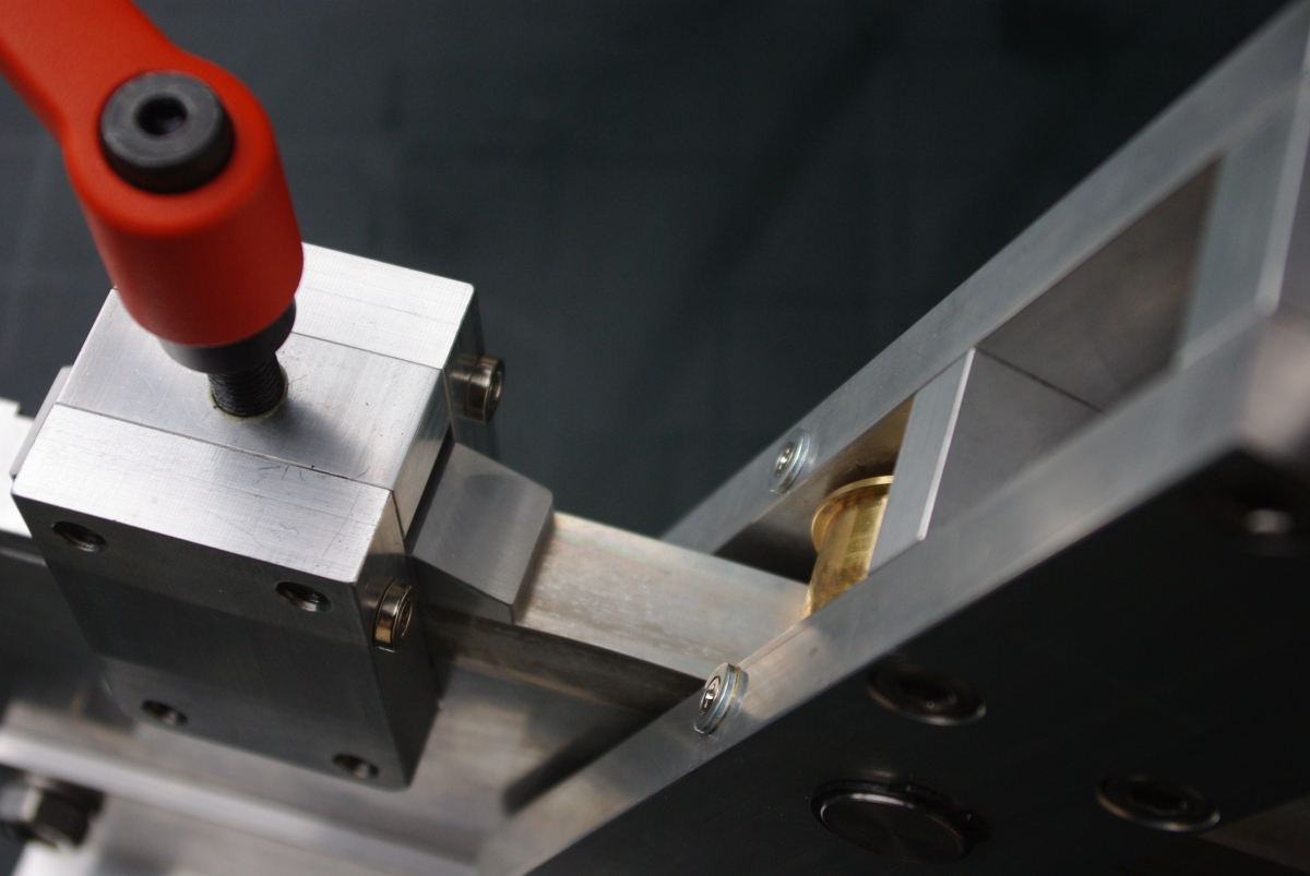
View from above:
• An aluminium plate T = 5 mm on one side
• One half of a boom connector on the other side
to reinforce the strut where to boreholes pass thru
and to level out force transmission
• Bolted together with 2 x M6 screws and self locking nuts
The pole is sitting underneath the boom and strut
to keep symmetry in the arrangement and pattern.
|
This strut is bent from a single beam of aluminium to produce increased stability. Bent little by little and adjust stepwise.
H-Frame by John, ZS6JON with Yagi booms centered nicely in line with frame parts to minimise pattern distortion

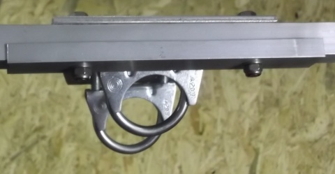
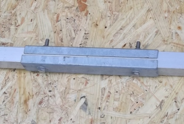
Boom Joints
joining 25 x 25 mm booms: Solid clamps made from 2 mm steel, galvanized.
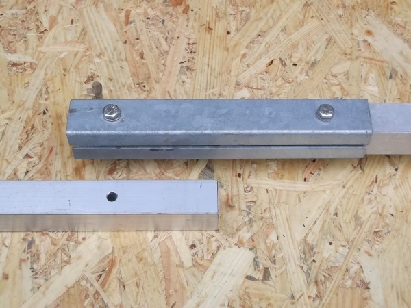 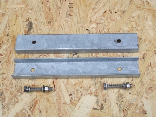
Boom ends are covered for 100 mm each
Length is 200 mm, screws M6 stainless. They are hand made by cutting pieces off
a stretch of a rectangular mild steel profile 30 x 40 mm with I cut into two pieces ...
Attenzione!
Drill holes large enough to enable mounting even under slighly dispaced bores - I use a diam. of 6.8 mm here.
Attenzione!
Boom joints and screws should be at least as ridgid as the boom itself.
73, Hartmut, DG7YBN

|
|