-
• Main Page
- • Home • Building
-
- Boom CorrectionIntro to Boom Correction and complete Collection of Factors
• DL6WU / G3SEK formulas and charts in detail
• DJ9BV insulated through boom
• I0JXX insulated through boom
• K1FO insulated through boom
• VE7BQH Cushcraft & Cudee on Boom
• DG7YBN semi-insulated on Boom
• Intro to SM5BSZ's BC.exe
• Segmentation Issues and more ... - Symm. & BalunsSymmetrising Devices from Sleeve Balun, F9FT Tube, EMI, G0KSC, Pawsey, 50 ohms Quarter Wave Line to 12.5 and 28 ohms DK7ZB Match ... plus Test Equipment - the RF Current Meter
- Phasing & Matching LinesHow to measure coax stub lines, produce coaxial impedance transformation lines, Baluns and how to stack and match with coax lines
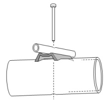
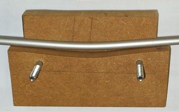
- Howto - Bent DEHow to bent a GTV Yagi DE with a simple selfmade tool:
Bending aluminium tubes by hand leads to buckles and brocken tubes. So I show what a simple selfmade tool looks like. You will need just a piece of wood, a few minutes and a jigsaw to produce one.
It will make the job much easier.
DIY - Bending Tool
- Building a YagiA collection of building hints - from DE-Box to bending Support Struts and mounting Elements. - Under Construction -
- Boom StrutsA collection of building hints - Planning and bending Support Struts and making bending tools. - Under Construction -
- Scaling Yagi ElementsHow to scale complet Yagis in Frequency and Element diameters from one dimension to another by hand
- Boom Correction


Symmetrising ⁄ Transformation Lines & Baluns
Quarter Wave DevicesHalf Wave Balun for Folded Dipoles
Common Mode Currents
Odd multiples of λ/4
How to measure current on coax shields
Applied concepts, examples, photos
Preface: About the importance of right coax and stub lengths
 Attenzione!
It is understood that a length of coax cable needs to be shortened using its velocity factor if we want to cut a resonate length. A waves speed in a medium is described as
According IEC 60250 the dielectrical constant of (natural) PTFE is εr = 2.1, measured at 1 MHz equalling v = 0.690 = 69%. However Radio Amateurs mostly use v = 0.7... 0.71 so that the calculated length of a 144 MHz Quarter Wave Line is around 369 mm.
But have you ever measured the resonance frequency what you have cut? At VHF and above you will probably be surprised to find your stub being some 5...10% too low in resonance frequency. This is due to εr and v-factor being specified´at a much lower frequency and plastics dielectrical properties are frequency depending to a certian extend.
An example
Subject is the 144 MHz YBN 5 ele. with Folded Dipole - engaged in elements-on-boom BC measurements for 30 mm round boom. It should have its best Return Loss at around 144.300 MHz, but as works are in progress it has slightly too less BC on it right now.
(1) A plot with Half Wave Balun using wrong coax length, as cut to "common" v-Factor valid for around 1 MHz
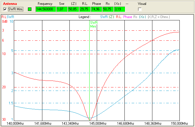
(2) A plot of the identical Yagi, only this time with Half Wave Balun measured and trimmed to 144.2 MHz = 38 mm shorter, delta is 500 kHz. On a λ/4 line based symmetrising device it would be half the influence in both length and derivation of SWR peak.

Why does the difference matter? Because if you acheive the right SWR through a too long Balun, symmetrising Match or Quarter Wave Line this Yagi will have too short elements. Which will result in less gain and in any case not the designed pattern properties. If I had not been aware of that mechanism I would have most probably added just a +1 mm of BC were it takes +3.2 mm in reality to bring the Yagi down to 144.30 MHz from were is at the moment.
And this is exactly the way some of the most followed designers of VHF and up Yagis have it and thus ignore the need for a precise Boom Correction or come up with ultra high segmentation numbers for standard Yagis where in reality a too long symmetrising coax brings down the Yagis frequency plot to about where it shall be.
Now it is clear that verifying NEC model segmentation densities corresponding to real world builds and needs for BC and their lengths will lead to misfitting readings when using lines cut to v-factor only. If one starts to modify the DE's length and D1 upon that the "drama" just proceeds.
How come? The excess length of the symmetrising member will add to the DE's length and virtually prolong it so that the electrical length will appear as being equal to a real length that is several millimeters longer then planned, modelled or cut.
 Find more information on my 'Phasing & Matching Lines' website
 Classic Style Sleeve Choke or "Bazooka" Balun
• The Sleeve Choke is a Current Balun.
Grounding the sleeve tube to the coax shield results in a series circuit. Any unbalanced current 'sees' the high impedance on the Driven Element side of this λ/4 line - thus seeks an 'easier way' to escape. Which is stay on Driven Element and be radiated.
A special challenge, additionally to get near and far ends of the sleeves tube waterproof, is to get the velocity factor i.e. shortening of the sleeve pot and that of the coaxes outer shield rigth. The dielectricum between these is air. Almost, since a bit of this cross section is covered by plastic - the coax lines outer insulation.
Second challenge waiting is how to get close to the Driven Elements terminals and not interfering with boom or parasitic elements. Which means close enought to the Driven Elements terminals to not ot be forced to connect with interfering pigtails lengths from open coax end on.
I have seen some nice solutions done with larger diameter coax shield stuck over thinner actual feeding line coax.
F9FT (Antennes Tonna) Style Sleeve
• The coupled sleeve is a Current Balun.
This derivate of the classic Sleeve Balun slips around most of the challenges mentioned above. This simplified version consists of a tube of λ/4 length, put over the feeding line coax as close as possible to the Driven Elements terminals. Its far side is connected to the boom. The sleeve tubes length must fit λ/4 electrically. The only way to determine this properly seems to be thru accurate measurements. The connection to boom shall be low impedand.
A test of this device for 144 MHz conducted by Tomas, OH6NVQ with a HP 8753A:
A 502 mm long tube of Ø 15 mm, wall thickness 1.5 mm with a Coax Tellu 7 by Co. Draka (75 ohms, Ø 11 mm),
the tube placed 6.5 mm above a 25 x 25 mm aluminium L-profile measures at -35.5 dB.


Photo credit: OH6NVQ, tnx Tomas!
Pawsey Stub Symmetrising Device
Having mentioned the challenge of matching both lines lengths to λ/4 electrically in the above classic Sleeve Balun concept - here we have similar conditions or constraints on both ways when using similar coax. Nevertheless the extra lines length must be shortened by the amount of what the far sides to shield connection will introduce in inductance.
EMI Stub Symmetrising Device

This dipole is part of a GTV 70-30m Rope Yagi which did successful 70 cm EME with 60 W at feed

EMI stub on a 432 MHz bent Dipole, photo on courtesy of Thomas, M0ABA
Practical EMI stub on a 70cm GTV70-14m by Mike, G3LGR.
He does successful QRP EME with just 80 W with it:

What is said according the Pawsey stub is valid for the EMI stub too. With the exeption that here the second coax is reduced to any sort if wire or metal rod or tube - for which the exact λ/4 length needs to be determind. Maybe with a dipmeter. Due to skin effect a decrease in travelling waves velocity will occure if that strip is clad with plastic insulation (see top of page).
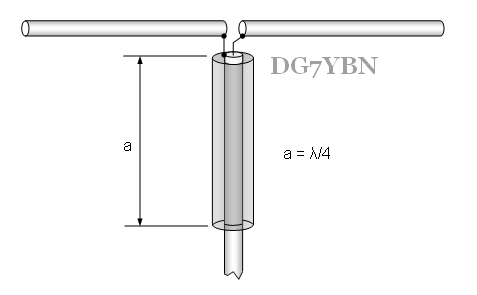
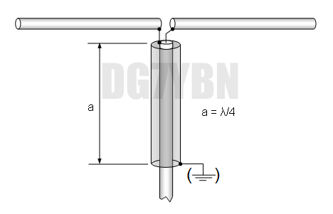
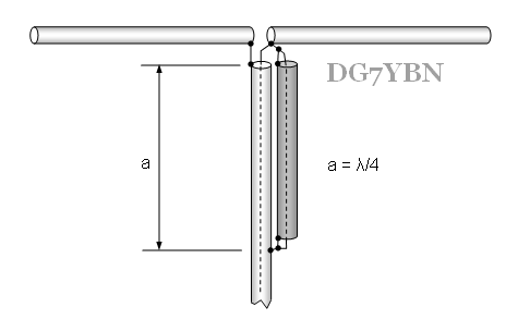
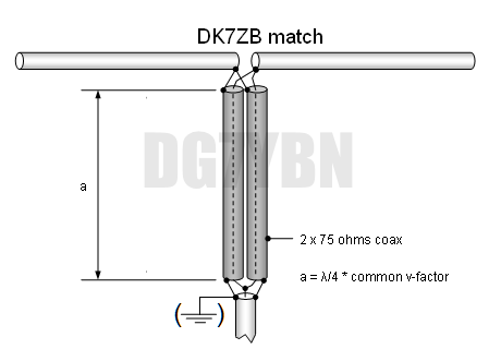
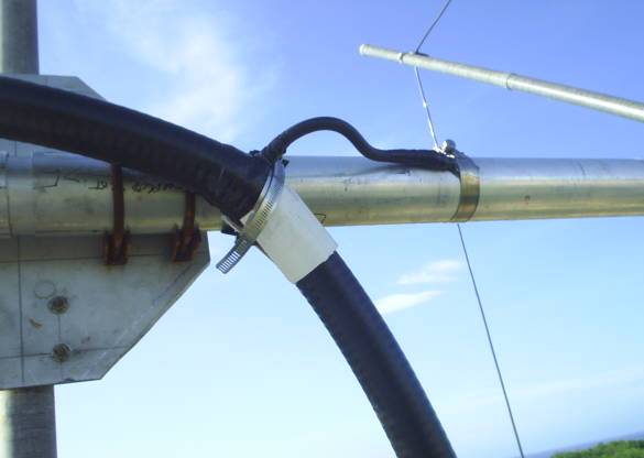
'Grounded' Coaxial Quarter Wave Line
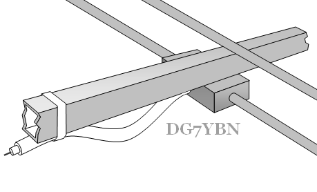
DG7YBN Style Quarter Wave Lines
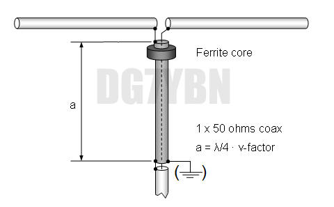
However a serious low impedant ground is hard to find on a Yagi-Udas boom high up in the air. This device needs a conductive boom
and a metal pole or mast with a mast clamp that at least enables some contact. And a ferrite core added to the near driven
element side of the 1/4 wl line. Which has to show a reasonable impedance / permittivity to block common
mode currents that aim to leave the driven element on the coax braid.
For more read see here Matching line length: Case 1 - using coax with plastic dielectricum
The Quarter Wave Line is trimmed to λ/4 * v-factor. Thus the inside of the coax stub acts as a resonate λ/4 circuit while the outside way is too short to provide a full λ/4. Blocking the outside way for HF by putting on a ferrite core excludes coaxes outside 'escape lane' for common mode currents. If they want to go down the coax they will have to use the inside now. Which is of fitting length to provide same mechanism as shown in all the examples above. Find further explanations and building hints here
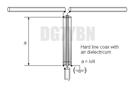
Matching line length: Case 2 - using coax with air dielectricum (EA1DDO version)
When using hardline coax with mostly air and few plastic spacers only as dielectricum, like 1/2" or 7/8" Air Flexwell or 5/8" Air Andrews, the velocity factor moves up to around 0.93 ... 0.97. Now inside and outside length to form a λ/4 are almost even. Hence the ferrite core blocking the outside way can be omitted if the connection to ground i.e. boom covers the little bit of outside length missing.
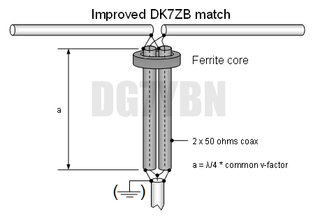
A Pro Version of the Coax Quarter Wave Line
While the common build with one ferrite core as close as possible to the dipole terminal is way good enough for most purposes adding more ferrites results in a higher grade Quarter Wave line.
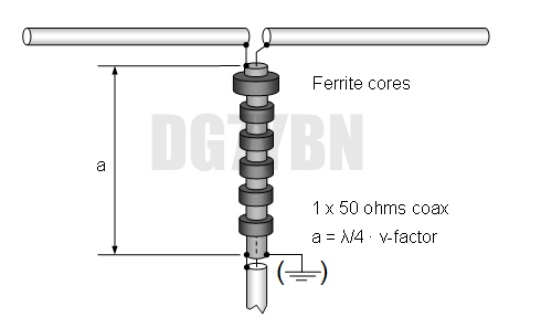
This (case 2) is what EA1DDO noticed and derived a new variant of this Quarter Wave Line symmetrising member from.
Find photos of the applied EA1DDO line below
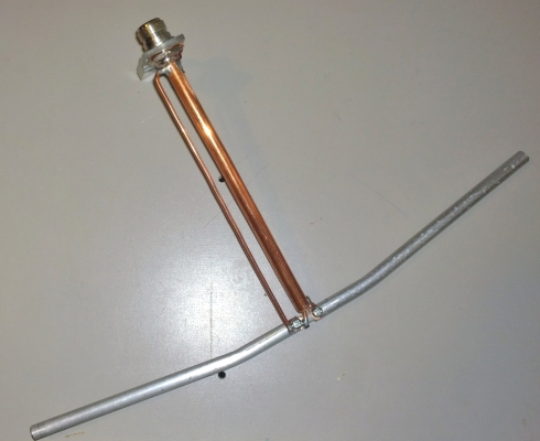
Coaxial Rigid Quarter Wave Line
Line made from copper tube by Thomas, M0ABA
Note the tight shape around boom of split ends and useful "push-point" for the 1/4 wave length at the grounding side created by not soldering the full circumfence of the copper tube end to the N-bushing but using copper wire for that (the Blade Dipole is an adjustable test version for finding the exact shape needed here).

Etched Quarter Wave Lines on PCB
Basically any RF line - no matter what physical realisation or make - can transform or symmetrise if of fitting length, Z and form. We find striplines of 50 ohms, 75 ohms or other Z in transverters and other UHF devices. Why not make one for antennas?
In doing so we can overcome the challenge of producing lines from paired coaxes as needed as 2 x 75 ohms for matching 50 / 28 ohms where there is no coax of 37.4 ohms or anything near that Z available. Furthermore we can break free from designing Yagis with feed point impedances quantised to combinations of available coaxes for transformation to feedline Z as a PBC bound transformation line could be layouted for virtually any transformation ratio.
Another reason for applying a quality PBC transformer might be accuracy and reproducibility as well as performance when using PTFE substrate We can easily deduce that for a bay of Yagis on 432 or even 1296 MHz every millimeter of similar and exact lengths will count on every single Yagi from tip to tow. Which will be much easier acheived etching 8 PBC instead of wrestling 2 x 8 pieces of 1/4 wl Sat-TV coax.
A sketch of that principle for use in a UHF Yagis DE-box
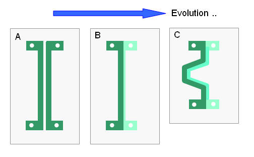
• It is clear that the line, in order to function as a transformation line must be of a quarter wave length or odd multiples.
For low Q performance even 1/3 of 1/4 wl might do. Width of stripes and their distance in combination with the substrates
v-factor will determine the lines Z.
• (C) shows a curved line; which holds two benefits: 1. we derive a more compact PBC dimension which makes it easier to fit it into the DE-box
2. we introduce some inductivity that may act as a bit of a choce balun. Keep in mind that we aim for a two-in-one functionality.
namely transform between antenna and feedlines Z and to symmetrise. Which a grounded QW line does in principle, but a little
support for this task is always welcome.
A real world completion for matching 50 to 28 ohms on 432 MHz by OK1VPZ.
Reported Return Loss is -24 dB approximately.

Vladimir states: "the microstripe PCB is made on double sided FR4 board with 0,8mm thickness"
For the full article by Vladimir and PCB layout on www.ok2kkw.com
50 to 28 ohms Coax Quarter Wave Concept
This Symmetrising Member transforms from 50 to 28 ohms as shown above and symmetrises. It is a two-in-one.
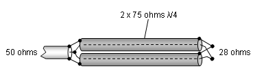
Grounding the two 75 ohm λ/4 lines on the far side leads to the DK7ZB Style 50 to 28 ohms Quarter Wave Line Match. The DK7ZB Match finds itself in same dilemma of non matching inside to outside coax lengths as the 50 to 50 ohms single line version. Martin Steyer explains that since two lines are engaged, they may introduce some extra inductance for extending the outside lengths to an approximate λ/4; especially when folded. He adds that using foam coax with higher velocity factor is to be prefered to minimise that inside / outside length mis-match.
50 to 12.5 ohms Coax Quarter Wave Concept
What is said according the 50 to 28 ohms Coax Quarter Wave Concept applies to the 50 to 12.5 ohms concept too.
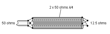
Grounding the two 50 ohm λ/4 lines on the far side leads to the DK7ZB Style 50 to 12.5 ohms Quarter Wave Line Match.

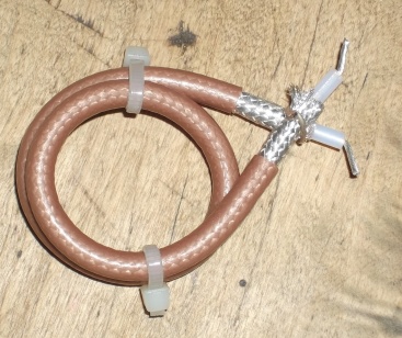
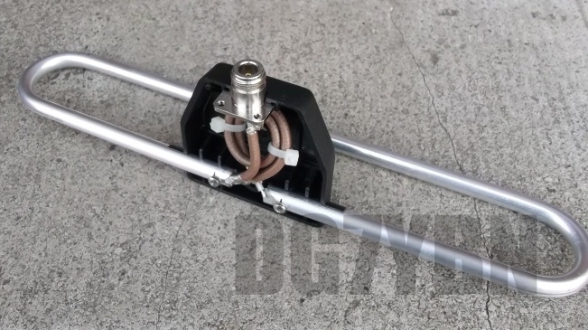
• 12.5 ohms to 50 ohms dipole box by IZ1AZA:
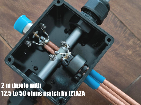

Photos: Kindly provided by IZ1AZA. Tnx Alex!
Classic half-wave loop Balun for Folded Dipoles
How to transform from 50 ohms to 200 ohms to feed a Folded Dipole as Driven Element
|
|
Attenzione! The half-wave loop is a Voltage Balun. It does not represent a Common Mode Choke. |
Scheme

The transformation ratio of a Half Wave "Diversion" Line is 1:4.
|
|
Attenzione! Mind the height of a folded dipole shall be no more than 0.05 λ. If that is exceeded it turns into some sort of full wave loop and leaves its natural 288 ohms of free space impedance to lower numbers. |
Measured lengths for RG-142B/U PTFE coax are 700 mm flat for 144 MHz and 231 mm for 432 MHz, from end of shield to end of shield. The excess length of the unshielded ends adds to the Folded Dipole. I advise NOT to electrically connect the balun to boom.
432 MHz Balun made from RG-142
See my article "Applied Conversion of Segmented Wires from NEC to 144/432 MHz Yagi Elements, Part 4 - Simulating the Folded Dipole", Dubus 1/2012
Common Mode Currents
Where do Common Mode Currents emerge from, and how large must a ferrite core be?
The magnitude of Common Mode Currents depends on how symmetrical DE and Yagi and enviromental influences are in the very case of your build. Even on the feedline of a dipole that is geometrically perfectly symmetrical we will find common mode currents. The more if it is not placed at least one or two wave length above ground.
Note the dotted circle on right side ... a missing few millimeters on one arm of the DE. Which symbolises a large part of the unbalanced bits from splitting the coax on. Like a little longer one side of the split coax, a close by metal part on the mast, whatever.
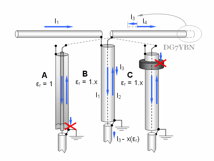
Case A: Air as Dielectricum, same electrical length inside / outside : both valid QW lines
Case B: Plastic Dielectricum, oridinary coax, if inside is 1/4 lambda outside is too short per 1/v-factor.
Case C: Blocking common mode current that sees lower resistance per not 100 percent 1/4 lambda on outside
However "a low impedant ground is NOT available [on aerials] high up in the sky" (K6STI).
So that at least a conductive boom and mast must be used with 'grounded' lines as symmetrising members.
Plus a suitable ferrite core which keeps most of the 'want to be' common mode current away from the coax braid
already.I like to add that in consequence an other device then the 'Grounded' Quarter Wave Line should be used in theory. Like a coax choke if it would not be so difficult to compensate all inductance and stray capacitance such a wound up length of coax holds. Aiming at best Return Loss we find other challenges in the appart from this issue theoretically very suitable Pawsey and EMI stub. Which for best functionality depend on the right electrical length of their 1/4 wl side member.
Read more on dimensioning practical builds of the QW-Line symmetrising member and right Ferrite Core here
What to avoid feeding a Folded DE
Tape it to the boom right from the connector or box on, or leave it hanging for much longer than λ/4 x v-factor.
Note: Any odd multiple of λ/4 such as 5/4 λ or 7/4 λ will transform exactly as the sole λ/4 line. Why so?
Because a half wave line does not change anything, apart form losses. Any odd number of λ/4 can be seen as a number of half wave lines plus a single λ/4 wave line.

The clip-on RF Current Meter
Much has been muttered about how to balance/unbalance correctly here and elsewhere. Who really wants to know needs to measure. Not only to find theory confirmed but control a finished builds constuction.
Looking out for some suitable method I found G3SEK's website on clamp-on RF meters. The basic idea is to couple closely to the feeding line coax shield using a clamp-on ferrite with a coil wound onto to grab some current running on the shields outer side. Here is my interpretation.
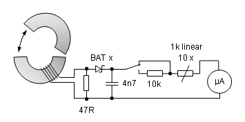
I added a switch that leaves my device with 'low' and 'high' power range plus a 10 turns 1k potentiometer for adjusting to some reference level. That may either be a known power into a load or a common mode current produced at certain fed in power returned by a reference antenna.
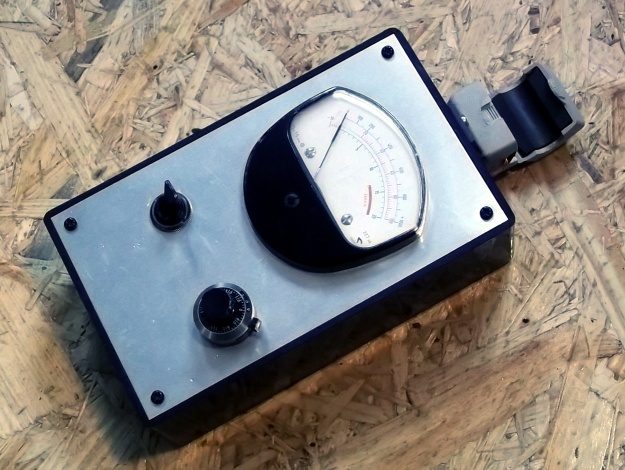
And this is what it looks like
Follow the link to G3SEK'S website
Applied EA1DDO concept
Maximo, EA4DDO wanted to help a friend to feed a 28 MHz 4 element Quad using the grounded Quarter Wave Line after he saw me promoting that basic concept in "Applied Conversion of Segmented Wires from NEC to 144 MHz Yagi Elements - Part 1", Dubus 2/2010
The challenge: this Quad was to be fed with serious QRO. So ferrite core sizes would have been immense, gamma match C's would fail, choce baluns thin coax probably melt down
... not so using the quasi direct feed with Heliax 1-5/8" hardline coax this method enables.
Maximos solution
Close Up on how the QW-Line is grounded
Photos by courtesy of EA1DDO
Source: http://www.ea1ddo.es/balun/balun_ea1ddo_para_antenas_cubicas.html
73, Hartmut, DG7YBN