Surplus Coax Relays
Coax relays, LNA & Combination of two Relays
Radiall 562720
A typical surplus relay. I have bought 2 of those for approx. 30 EUR each.

Port Isolation (Analyser: Planar TR1300/1)
Data:
 • Coil: 12 VDC, Connectors: 3 x N female

Freq. (MHz)           50.1       144.1       432.1         1296.1
Insertion Loss        n.a.        n.a.      0.04 dB          n.a.
Port Isolation       -45 dB      -36 dB      -28 dB       (- 41 dB)
RelComm RDL SR012
A high spec. coax relay that can be found at surplus resellers for less than 70 EUR.

Port Isolation (Analyser: Planar TR1300/1)
The RelComm is said to have >110dB isolation on 144 MHz and >90 dB on 432
And this is what my Planar VNA gets of it, bubbles and waves at the bottom line of its dynamic capability beyond -90 dB

Data:
 • Coil: 24 VDC, Connectors: 3 x N female

Freq. (MHz)           50.1       144.1       432.1         1296.1
Insertion Loss        n.a.    > 0.01 dB     0.02 dB       0.04 dB
Port Isolation    >> -80 dB   >> -80 dB    > -80 dB     (> -80 dB)
Reference Data: CX-520D and CX-600N
Factory Data, Source WiMo Website:
 • Coil: 12 VDC, Connectors: 3 x N female

Freq. (MHz)             50        150         500         1500
Tohtsu CX-520D
Insertion Loss      -0.1 dB     0.15 dB     0.18 dB       0.2 dB
Port Isolation       -65 dB      -60 dB      -53 dB       -42 dB

Tohtsu CX-600N
Insertion Loss     -0.07 dB      0.1 dB     0.15 dB       0.2 dB
Port Isolation       -60 dB      -48 dB      -37 dB       -26 dB
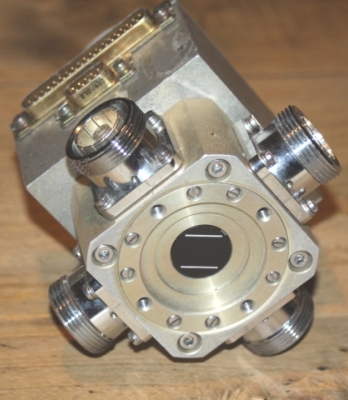
Spinner BN 51 26 70
A QRO surplus relay for the ambitioned amateur ...
because it shows two prime disciplines in a nice pairing: very low insertion
loss as essential for EME reception and same time real QRO power rating.
This device actually is a rotator commutator ring type switch, driven by an
impulse solenoid (magnet actuator) with internal eletronic control. A kind of
90 degr. per impulse / step stepper drive. Hence ... no full BK. Switching time is < 0.1s

Port Isolation (Analyser: Planar TR1300/1)
Data:
 • Coil: 24 VDC 2.25A, Bistable, Connectors: 4 x DIN 7/16 female

Company Specs BN 51 26 70
Freq. (MHz)           0 ... 1 GHz       ... 1.4 GHz         ... 5 GHz
Reflection/VSWR       < 1% / 1.02       < 1% / 1.04         < 2% / 1.22
Isolation             > 90 dB           > 80 dB             > 65 dB


Freq. (MHz)           100 MHz         230 MHz         ... 3 GHz     ... 5 GHz
Power Rating          < 5 kW(x)       < 3.5 kW(x)     < 2.0 kW      < 0.7 kW
Switching Time        < 100 ms
(x) Successor BN 51 26 90 Data

Own Measurements
Freq. (MHz)             50            144           432           1296
Insertion Loss       < 0.01 dB     < 0.01 dB      < 0.01 dB      0.01 dB
Port Isolation         -95 dB        -92 dB         -91 dB       -78 dB
A QRO Relays with 3 x DIN 7/16 Connectors
A heavy duty relays, true surplus (hi), unknown make, history and original purpose

Port Isolation (Analyser: Planar TR1300/1)
Data:
 • Coil: 220 (230) VAC, Connectors: 3 x 7/16 female
 • Dim: 135 x 130 x 107 mm incl. coil

Freq. (MHz)           50.1       144.1       432.1         1296.1
Insertion Loss    > 0.01 dB  > 0.01 dB     0.02 dB        0.03 dB
Port Isolation       -50 dB     -41 dB      -32 dB        (-34 dB)
How to arrange Coax Relays and LNA on Mast for serious Weak Signal Works
Is is clear that the LNA needs to be as close as possible to the Antenna Terminals in order to minimise cable
losses. Instead of adding a pair of coax relays to the PA and to the LNA too here there is a fool prove concept
for with you need a separate thin coax line but just one expensive quality coax relay:
PA, Filter, LNA into our setup. Only the coax relais on the mast needs to be of high quality, low insertion
loss, (QRO) power handling ability and high port isolation type. The other one down in the shack or
installed in the PA cabinet can be a low cost type.
The mast mounted coax relays and LNA can be supplied with DC voltage by a single wire carrying
13.8 or 24 VDC when RX is on. Making the coax relay switch to the RX side and same time supply the
LNA when rx-ing. So that when TX is on the coax relay drops off and LNA is off too.
Which basically makes this a fail safe and simple circuit. Losing the control wire or 13.8 VDC supply
or 'RX-on' from your sequencer ... with no distressing consequences but both your coax relays droping off
and connecting the (un-fired) PA to the antenna.
RelComm RDL SR012 with 432 MHz PHEMT LNA
A nice pair - ready to be housed for on mast mounting
A capable combination of LNA with PHEMT, measured NF = 0.28 dB, OIP3 = 19 dBm and a low loss,
high port isolation coax relay. So that the power limit is determined just by the N-Connectors.

With that arrangement I get 1.5 to 2 dB of sun noise on 432 MHz with a single 17 ele. EF7017 (YU7EF)
and 6 m (!) of Aircom Plus between Yagi and ULNA at an SFI of around 140.
Switchbox with 24 V Coax Relay and 12 V LNA
Using Surplus Relays one often will find them to operate with 24 V while the LNA needs to be supplied with 12 V or less.
Even if the LNA could stand to the 24 V, the low noise transistor will operate with 5 volts only. So that the difference in voltage
will be converted into HEAT inside the LNA's housing. If your high IP transistors bias current is high or the total circuit consumes
50 mA then you have around 0.85 W of heating up the LNA constantly during RXing. Which easily can cost 0.1 dB of noise figure.
Let this heat dissipate outside the LNA. Which is no problem in this application since we only need it when RXing. When TXing it is
not even supplied but just passive.
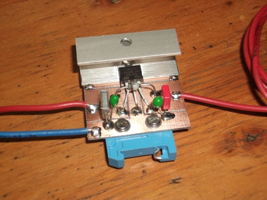

Supply your LNA with the lowest adequate voltage by inserting a DC/DC converter. But make shure that the ripple voltage is very low
by adding a suitable number of C's to input and output. This 'open' design would propably fail when QRO TX power is applied (!) though the
voltage regulator is somewhat sheltered from RF by the U-shaped heat sink.
And finally - the completed switch box, note the DC converter on right side as a module on the click-on-rail. The PA is connected to the antenna port via the
"Normally Closed" and the RX-side via the "Normally Open" contact. The whole box is without DC supply on TX. Feeding 24 V lets the coax relay pull to the RX contact plus
supply the LNA. So that this is pretty simple but fail safe.In case the DC control line breaks up nothing blows up but your coax relay connects the PA to the antenna

Surplus Combination of large 3 x 7/16 Relay followed by Radiall 562720
For using the heavy 3 x 7/16 coax relay on 432 MHz and higher with QRO we need a port isolation
in excess of -50 dB to restrict the passed over power to > 10 mW when transmitting with 1 kW.
Either we buy a capable coax relay for EUR 350 and up ... or we add a second coax relay into
the RX port.

the safe side. BUT ... port isolation is not the only numbers that add. Losses do too.
Due to sizes and location of connectors we can not just connect these two directly. We need a
number of adapters to get there.
What losses do pile up here? Is an arrangement like this feasible at all?
Data (including 1 x 7/16 90 degr., 1 x 7/16 male-male, 1 x 7/16-to-N adapters as shown on photo):
 • with Radiall 562720 as follow up relay

Freq. (MHz)         144.1       432.1
Insertion Loss     0.08 dB     0.15 dB

 • with RelComm RDL SR012 as follow up relay

Freq. (MHz)         144.1       432.1
Insertion Loss     0.08 dB     0.13 dB

 • Radiall 562720 as follow up relay connected with short coax cable (2 x N)

Freq. (MHz)         144.1       432.1
Insertion Loss     0.12 dB     0.18 dB
How much degradation of our RX performance on 432 MHz will that mean?
We estimate a 4 Yagi Bay of 19 ele. Low Noise Yagis with an Antenna Temperatur of 30 K
and an LNA with an NF of 0.28 dB / gain = 18 dB plus 1.5 m Ecoflex 15 between Antenna Terminal and the coax relay.
May the Receivers NF be 7.0 dB as a typical number for standard rigs.
 • With the RelComms insertion loss of 0.02 dB we yield

an RX Noise Temp. of 69 K = NF = 0.93 dB
a System Noise Temp. of 99 K = NF = 1.28 dB

 • With the added up insertion losses of heavy duty relay, Radiall relay and all adapters we yield

an RX Noise Temp. of 83 K = NF = 1.09 dB
a System Noise Temp. of 116 K = NF = 1.42 dB

(all data computed with VK3UM's EME Performace Calulator, Vers. 8.05)
73, Hartmut, DG7YBN