High Power Low Pass Filters
Band Pass Filters
Surge Protection OR Notch Stub
A Duplexer
144 MHz 5 Pole Low Pass Filter (LPF) for several hundred Watts
This filter I have build to clear the output of a 350 W LDMOS pallet amp. from spurious and harmonic waves
Plotted with a Planar TR1300/1 Analyser
Loss between ports due to the two coax cables is 0.84 dB. Loss with LPF included is 1.05 dB.
Which leaves 0.21 dB of insertion loss on account of the LPF.
3rd harmonic = 432.3 MHz is damped by > -43 dB. Mission accomplished.
Some details and hints
 • Circuit Design DJ9KW, see here => http://www.dj9kw.de/dj9kw/projekte/afu/2m_lowpass/lowpass.htm

 • I used two Russian 'Doorknob' C's with 33 pF each, coils inner diam. = 10 mm, 1 mm CuAg wire

 • Box is a 114 x 63 x 54 mm cast aluminum case; vent. holes are diam. 6 mm

 • Losing 0.21 dB on 350 Watts equals a loss of 16.5 Watts which will heat up the box.

| Attenzione! Drill enough holes into the housing to enable sufficient air ventilation. A constant heating with 15 .. 20 W must be conveyed from inside of it to the outside world ... |
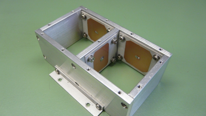
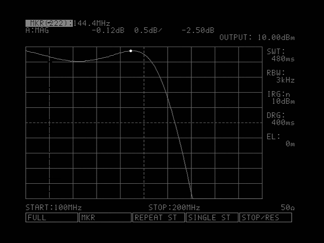
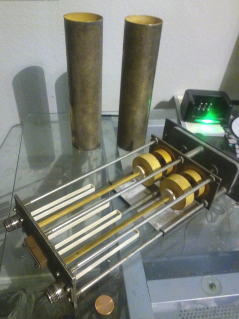
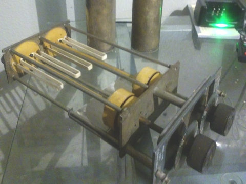
144 MHz 5 Pole Tschebyscheff Low Pass Filter for > 1 KW by DL2VL
This LPF was designed to fit into a 2m 600W LDMOS PA with a bit of reserve power handling ability.
Brief description:
• The short coax pieces are UT-250, 50 ohms PTFE semi ridgid, high power, low loss type.
Ø 6.35 mm (0.25 in), loss < 0.07 dB/ft @ 1 GHz, < 900 W @ 1 GHz
• Capacitors: etched on Rogers 4003C, thickness 0.02 in, the mid C is divided into halfs per chamber
• Coils: made from the core of a H2000flex coax, Ø = 2.62 mm
• by building the filter into 2 chambers with the mid C functioning as a feed-through capacitor
the filter steepness of this real built is increased.
• Data:
Filtertype: 5pol Tschebyscheff with a ripple of 0.3 dB
S11@144.4 31 dB(Return Loss)
S21 -0.12 dB (Insertion Loss incl. connecting coaxes)
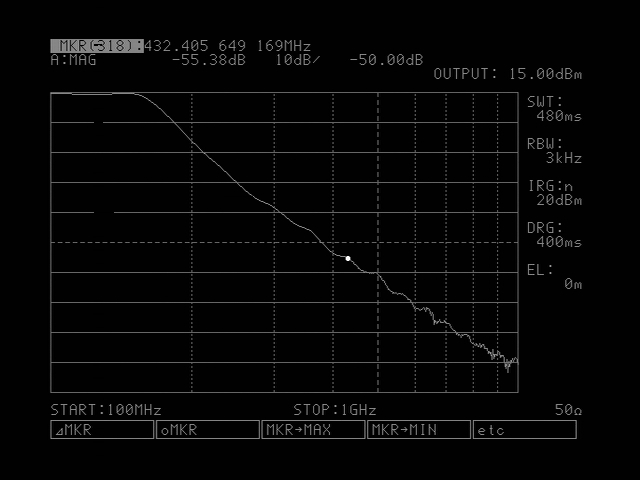
Attn. 432 MHz 55.5 dB
Attn. 864 MHz 87 dB
Pmax >1 KW
For these measurements an R&S ESVD was used. For full VNA plots see below ..
The build

The Scheme


(a) Simulation with RFSim99 (range: 100 - 200 MHz)


144 MHz 5 Pole Low Pass Filter for > 0.75 KW built by DL2FCN
Bodo, DL2FCN describes an LPF that handles the output of his 144 MHz GS35b PA.
Driven with 750 W key down for 1 minute the coils get but lukewarm Bodo states.
This filter is very easy to build, but performes well. The key to this is the remarkably simple
way the 2 capacitors can be produced.
The design follows the basic LPF schemes by
(1) Gerhart, DJ5AP, UKW-Berichte 1+2/2000, 'Tiefpassfilter für 2m und 70cm im Selbstbau'
(2) Günter, DL4MEA's paper 'A 144MHz Amplifier with a GS35b' which is based on the ON5FF LPF (DUBUS 3/85)
Making the Capacitors:
They are but aluminium plates, 58 x 67 mm held above the gnd sheet by ordinary Nylon (Delrin) M3 screws.
At a distance of 2.5 mm the required capacitance should be 18 pF each. Which will make up for stray
capacities from the near by box walls etc. It is clear that a 'microwave oven test' to see if the
to be used screws are capable is indespensible.
Making the Coils:
wire is Ø 2.5 mm CuAg
L1, L3: 3 wdg on Øi 11 mm, length = 17 mm
L2: 4 wdg on Øi 13 mm, length = 19 mm
Scheme: Photo - Dubus Magazine 4/2007 "QRO Lowpass Filter for 2m PAs" by DL2FCN


This design has initially been published in Dubus Magazine 4/2007 as "QRO Lowpass Filter for 2m PAs"
Coaxial 432 MHz LPF for about 200 W max.
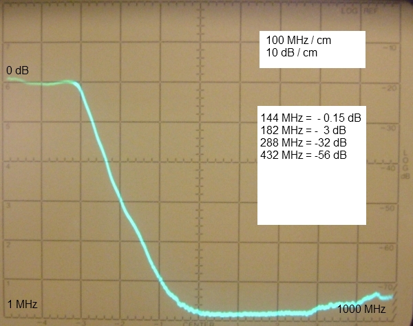
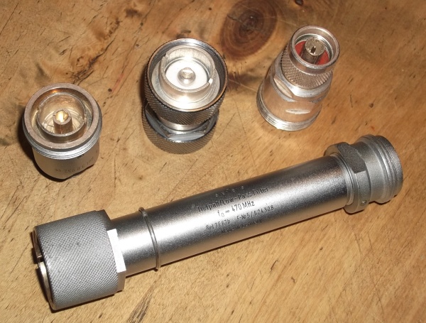
A commercially made coaxial stepped impedance LPF with 7/16 connectors
that holds a number of lumped inductances mixed with distributed capacitances.
Plot - Line losses included
Line losses only
So that loss on the LPF is 0,3 dB ...
which still includes the pile of connectors I needed to connect to the VNA listed below
1 x 7/16 male to N-female,
1 x 7/16-male to 7/16-male
1 x 7/16-female to N-male adapter
as to be seen on photo.
Make is "Siemens", Part No. Rel3F67b F-Nr.5/624308 - Tiefpass/Low-Pass Filter fo = 470 MHz
144 MHz 2 Pole Band Pass Filter (BPF)
144 MHz BPF from modified 417/GRC Receiver band pass filters
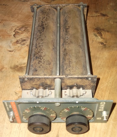
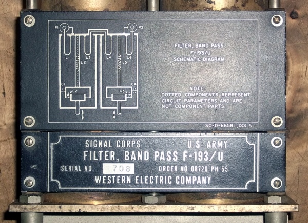
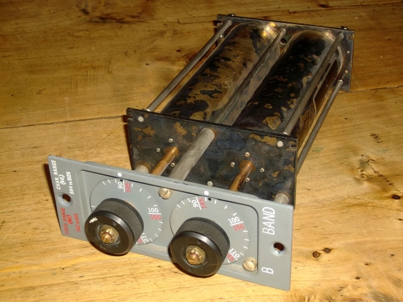
This is a plot of a commerially made two cavity filter 'Band Pass F-193/U, Signal Corps U.S. Army' for
the 'B-Band' (+/- 125-140 MHz) made by US "Western Electric Company". The cavitys are 198 x 63 mm each,
overall dimensions are 297 x 157 x 64 mm. It has 2 x N-female connectors on the backside.
If this filter must be modified to operate as a 2 m bandpass is not clear. It seems to work at least from
144.0 to 1446.0 MHz without any changes. However below you find a suggested modification as published in
the American Ham Radio magazine in 1980.
The shown filter is one out of a whole range of similar designed devices for other bands, see the table below.
They are also known as 'Rosenkranz-Filter' or 'Bandpass filters for 417/GRC Receivers'.
|
|
Those filters had been made for a number of commercial bands.
Here is table of 417/GRC BPF sorts and covered frequency ranges
Type      Freq. (MHz)       Type      Freq. (MHz)

F-238/U    50.0-58.5        F-196/U    184-205
F-239/U    58.0-67.0        F-197/U    205-226
F-240/U    67.0-76.5        F-199/U    224-254
F-241/U    75.0-84.5        F-200/U    254-284
F-242/U    84.0-92.5        F-201/U    284-314
F-192/U     100-121         F-202/U    314-344
F-193/U     121-146         F-203/U    344-374
F-194/U     142-163         F-204/U    374-404
F-195/U     163-184         F-236/U    550-600
Modifying those filters is largely and very explicite covered in the issue of the American magazine
Ham Radio (hr) February 1980, pg.42 - 46, in 'How to modify surplus cavity filters for operation in 144 MHz,
by William Tucker, W4FXE
It is a pitty that I must not add the full article for copyright reasons, but I like to thank James, AD5NL from
Austin, Texas for making it available to me. As this document is not on the internet but on microfilm only, he
had to send an email query to his alma mater, the University of Houston, and they did him a nice favor by
scanning the microfilm and e-mailing it to him.
And this is how several of these Filters can be converted to cover the 2 m band
The shown conversions are based on the ideas of W4FXE.
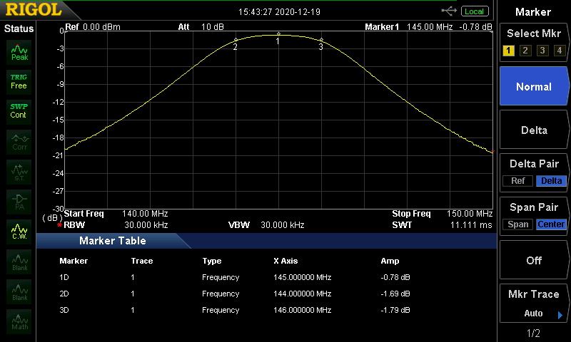
Converted F-193/U plotted with a Planar TR1300/1 Analyser
The shown loss includes the measurement coax lines (!)
F-194/U: S21 plot with trim to 144-146 MHz contributed by DG3HDA, tnx Hendrik.
Transmission gain is normalised to 0 here.
A F-194/U contributed by Volker, DF2YF the next shorter filter (142-163 MHz)
S21, filter curve at low end 137 MHz
Through damping loss is 1.88 dB - 1.35 dB = 0.53 dB see baseline plot of coaxes only (below)


144 MHz, 432 and 1296 MHz Surge Protection or vice versa Notch Filter Stub by DL2VL
Description
• This is not a 1/4 λ stub but so to speak its counterpart if used as a surge protection (short-circuited end)
• This is a high Q 1/4 λ stub if used as a notch filter (open end)
Surge Protection
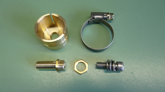
Jörg, DL2VL: => the end piece made on a turning lace is just a solid short circuit bit, which connects
conductor and braid at the end of the stub. By adjusting how far it is pushed onto the end of the stub the devices
resonance frequency can be tuned.
Notch Filter
Another use of this can be as a notch filter in the RX line. DL2VL measures a notch depth of ~ 45 dB
For making a notch filter chose a length of 1/4 λ and leave the end of the stub OPEN. For rejecting an FM transmitters
signal on 98 MHz (3.059 m) we use a length of 1/4 λ x V (= 765 mm x V) with an open far end.
Jörg, DL2VL: "Die Fa. Dehn verwendet auch dieses Prinzip, der Preis ist aber nicht für das HAM-Budget geeignet.
Die erreichten Daten in Bezug auf Einfügedämpfung und Durchgangsleistung sind besser als die der üblichen
Überspannungsableiter Gasentladungsstrecken.
Das Drehteil ist einfach ein "guter" Kurzschluss, der am Ende des Stubs die Seele mit mit dem Mantel verbindet.
Ist eben so ausgelegt, dass auch größere Ströme gegen Erde fließen könnten, die über die Schraube
und eine Kabel nach GND abgeleitet werden können. Je nach dem, wie weit er auf das Ende geschoben wird, wäre auch
ein Abgleich der Resonanzfrequenz möglich (ist aber eh breitbandig genug). Der Vorteil ist, dass die Seele immer geerdet
ist und nicht erst z.B. 350 V auf dem Innenleiter sein müssen, die eine Gaspatrone braucht, um zu zünden."
Als Notch Filter auf der Empfangsseite, um selektiv einen starken Störsender auszublenden:
Das wird dann auch als "Offene Stichleitung" bezeichnet. Diese "wirkt wie ein Saugkreis für die Störquelle".
(nach Rothammel, K., DM2AB, Antennenbuch, 8te Auflage, S. 538)
Surge Protection built by DL2VL
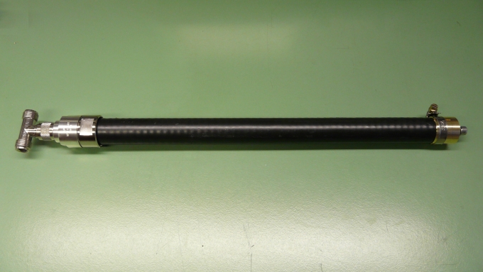
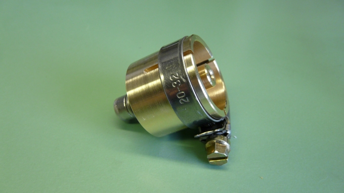

Data:
Stub 7/8" Flexwell Coax, length 402 mm
QRG 144 MHz and its harmonics 70 cm, 23 cm
Length 461 mm (from T-piece to short circuit point)
Loss 0,04 dB @ 144MHz
Daten:
Stub 7/8" Wellmantel Koax, Zuschnitt 402 mm
QRG 144 MHz, und die Harmonischen 70 cm, 23 cm
Länge 461 mm (vom T-Stück bis zum Kurzschluss)
Dämpfung 0,04 dB @ 144MHz
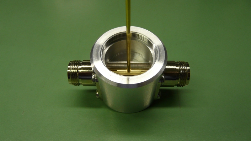
A Serious Notch Filter Stub by DL2VL
This Notch Filter provides low loss for the 144 MHz pass band and notches 432 and 1296 MHz.
With a Return Loss of 21 dB equaling a VSWR < 1.18 this Notch Filter is suitable for TXing.
Which is not the case with all Notch Filters. The key to this achievement is (a) a precise
make, and (b) least of impedance interstices.
DE: Kerbfilter, filtert im Gegensatz zu Hochpass- oder Tiefpassfiltern Frequenzen in einem engen Frequenzband aus.
Assembled Notch Filter: total length = 208 mm, aluminium tubus Ø: 30 mm, head Ø: 40 mm

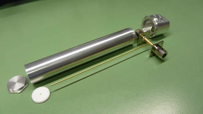
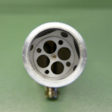
Tune-to-QRG is 432,6 MHz (3. harmonic of 144.2 MHz), here an S21 = 43 dB is realised
- S21 at 1/3 = 144,2 MHz is 0,12 dB
- S11 at 144,2 MHz is 21,6 dB
- The dampings maximum on 23cm does not exactly fit the 9ths harmonic of 144.2 MHz
- Tuning is realised through shifting the PTFE plate
- The plate's thinkness is 1,5 mm, it is suppies with holes to lessen its influence
- 150 ohms notch: core conductors Ø: 2 mm, outer Ø: = 24 mm, length of core = 170 mm
- 50 ohms line: core conductors Ø: 6 mm, outer Ø: 12 mm
Abgleich-QRG ist 432,6 MHz (3. Oberwelle von 144.2 MHz), hier wird ein S21 = 43 dB erreicht
- S21 auf 1/3 = 144,2 MHz ist 0,12 dB
- S11 auf 144,2 MHz ist 21,6 dB
- das Dämpfungsmaximum auf 23cm entspricht nicht mehr exakt der 9. Oberwelle von 144 MHz
- Der Abgleich erfolgt durch verschieben der PTFE Scheibe
- Die Dicke der Scheibe beträgt 1,5 mm, sie ist mit Löchern versehen, um den Einfluß gering zu halten
- 150 Ohm Notch: Innenleiter = 2 mm, Außenleiter = 24 mm, Länge Innenleiter = 170 mm
- 50 Ohm Leitung: Innenleiter = 6 mm, Außenleiter = 12 mm
Inside view ...see the notches core sticking out
Download a CAD Drawing of this 432 MHz 1/4λ Notch by Jörg, DL2VL

Photos, data, plots and drawing: with kind permission of Jörg, DL2VL
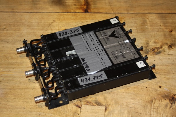
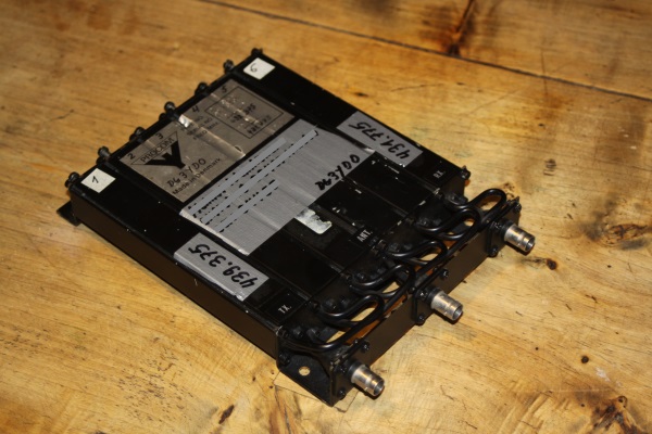
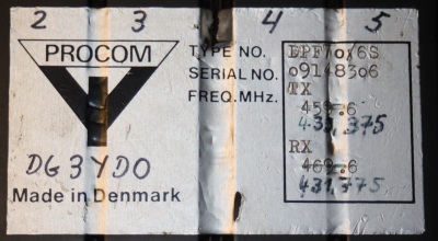
A Procom 6-cavity Duplexer for 459 - 469 MHz tuned to 431 - 439 MHz
This Duplexer shall serve for a 70 cm band repeater.
It has BNC plugs and M5 screws with counter nuts for tuning.
(both of which I did not enjoy much when tuning this DUT)
Tuned it is almost within actual Procom specs for the newer DPF 70/6 model:
>= -65 dB, SWR =< 1.5, loss =< 1.5 dB
Baseline Plot


73, Hartmut, DG7YBN