

Simulating the DL7KM Beam with Double Quad Driven Element
The DL7KM beam has a fan community on its own. Among those are a number of contesters.
I became curious about what would be in this design.
How good is the DL7KM Beam? - Some sources that report about its gain:
• K. Weiner, DJ9HO, UHF Unterlage, 1980: E.4.5.2 Der Doppelquad-Beam mit G = 15dB, (Engl.: UHF Compendium; The twin-quad beam on 2m) acc. to DL7KM - Gain = 15 dBD, HPBW = 33.5 / 30.2 degr, F/B approx. 25 dB
• A. Krische, DJ0TR, Rothammels Antennenbuch, 2013, : Gain ≥ 13 dBD, F/B approx. 25 dB, HPBW = 35 / 32 degr
• R. Bertelsmeier, DJ9BV: "Gain and Performance Data of 432 MHz Antennas (Leistungsdaten von 432 MHz Antennen)", Dubus 1989: Rainer attested the 70 cm version a forward gain of 9.75 dBD (11.90 dBi) only. But that is due to "badly mistuned directors, because of wrong scaling from the 2 m version. Cutting all elements will increase gain to 12.0 dBD, which is also low for this size."
Setting gain numbers of up to 15 dB over a dipole, that the DL7KM Beam is quoted with, in relations to RF physics:
At an identical boom length a single top ranking narrow band Yagis in the G/T List produces around 13.6 dBi. A pair of these Yagis needs to be stacked at a distance of 2.7 m to yield an additional theoretical gain of max. +3.0 dB. This is the spacing according the well proven DL6WU formula and we have not taken into account any phasing line losses. Summed up ... for a set of two sound Yagis of same length as the DL7KM Beam we can expect 16.6 dBi or scraping a 14.5 dBD in an optimistic view. And this with a significantly larger effective aperture area covered by a twined top today design. This said, it is quite unlikely for the DL7KM Beam to reach even that 14.5 dBD, with just less then half of stacking distance between the two booms. At that close distance of 1200 mm or 0.58 wl the twin booms of the DL7KM Beam are apart a typical stacking gain is just 1.4 dB. Which would leave our pair of closely stacked Yagis at 15.0 dBi or approximately 12.9 dBD. Which makes a contrast to the fabulous 15 dBD we see quoted here and there for the DL7KM Beam.Original design
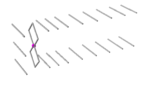
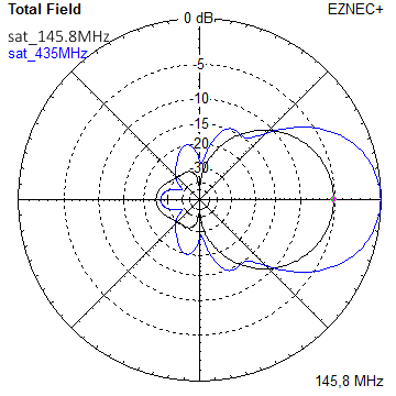
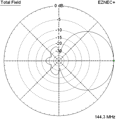
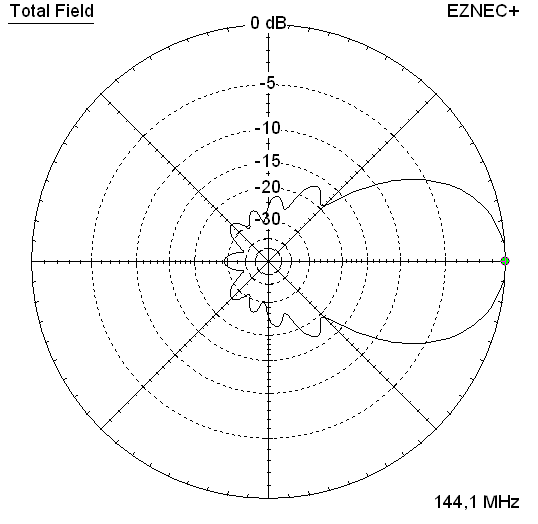
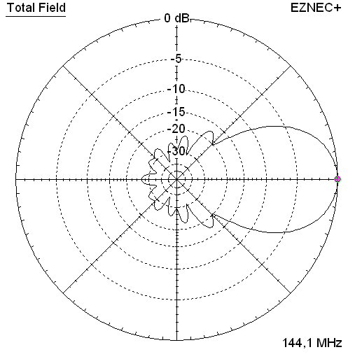
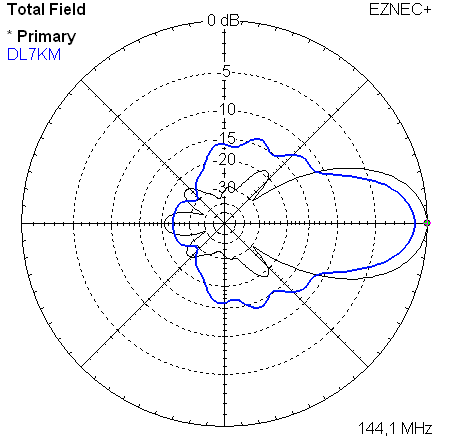
Gearing up ... with first simulated patterns at hand I immediately wished for a better pattern, as it
is commonly understood that under stacking leads to very clean patterns basically:
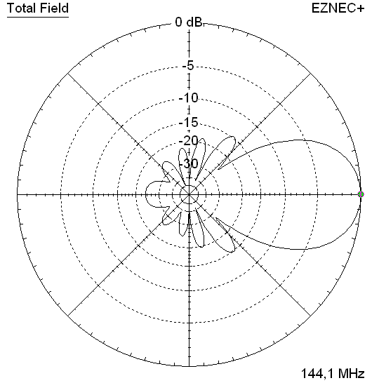
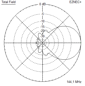
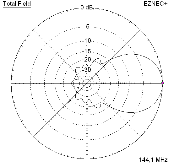
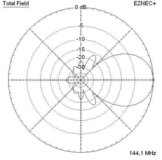
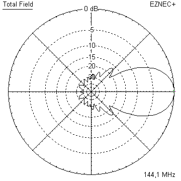
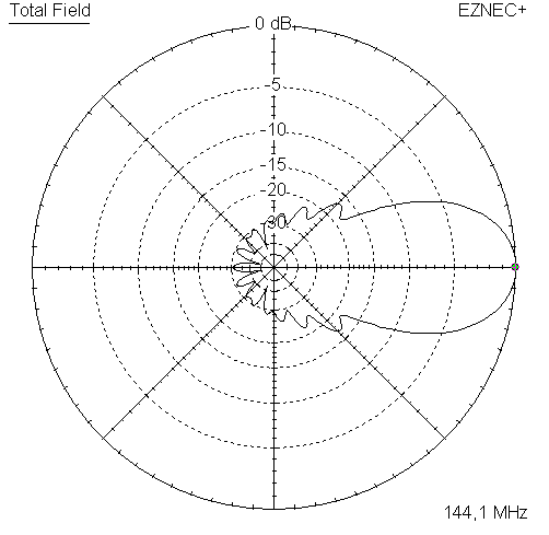
Original DL7KM Beam (blue line) vs. anticipated modified design (black)
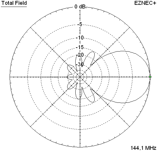
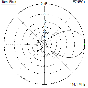
Simulated elevation and azimuth plots

Design modification
After setting up a NEC model and looking at the output with barely 12 dBD I decided to do a redesign that a build of the original beam can be adapted to. The outcome covers the full 2 m bandwith very low SWR and delivers consistant gain over the 2 MHz stretch. Same time it delivers at least 1 dB more gain and much less Antenna Temperature.
Modified design with small inner structure
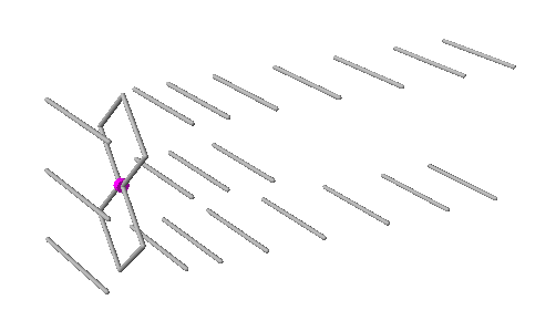
I elemininated one element from the wave guiding structure each, spread the remaining ones more sensibly over the boom length, modified their lengths, moved the reflectors closer in, and added three inner directing elements - which play a major role in tying up the beams pattern.
Performance Data of original and modified Design
                     Orig. DL7KM    Mod. YBN
Gain vs. isotr. Rad.  13.3 dBi*     14.8 dBi**
Gain vs. Dipole       11.2 dBD*     12.6 dBD
-3 dB H-plane         29.6 deg.     33.5 deg.
-3 dB E-plane         35.2 deg.     37.2 deg.
F/B                  -22.2 dB      -20.8 dB
F/R                  -14.9 dB      -20.8 dB
Impedance               60 ohms       50 ohms
VSWR Band Width       1.3?:1***     1.03:1***
Mechan. Length        3970 mm       3940 mm
Electr. Length        1.91 λ        1.89 λ

Corrected Average Gain Data for the single beam
(using 13.31 dBi of the orig. design)
T_loss                4.5 K           2.5 K
Antenna Temp.         313 K         235.5 K
G/T (single ant.)  -11.25 dB        -8.94 dB
*) Due to the Double Quad exciter and a little uncertainty caused by unknown BC for mounting elements directly conductive onto a 15 x 15 mm boom (as proposed by DL7KM in the UHF Compendium) the actual element length for the NEC model is not clear for the last 1 or 2 mm. The gain I quote for the original DL7KM Beam is an optimistic one because of all the challenges the design model holds for even the ambitioned NEC modeller.
Given that the Design was developed on an experimental base pre 1980 a BC is 'build in'. I have subtracted 3/4 of the BC that DL6WU gives for conductive through boom builds here.
**) 14.92 dBi at an Average Gain of 1.025 for the lossy model and 14.96 dBi at an AG of 1.034 for the lossless model. With AG correction per KF2YN applied the remaining gain is 14.78 dBi or 12.63 dBD.
***) as in VE7BQH G/T table = at 145.00 MHz
The Half Power Beam Width of the original design might suggest more gain then there is in it. Which is due to the unusual pattern characteristic compared to ordinary Yagi designs. Thus we meet a quite different form factor η_loss for the standard equation for effective area and gain:

With G(loss) = numeric gain including losses on wires. As the equivalent to multiplying the capture area A with η_loss on the other side of the equation. We produce G(loss) "automatically" when measuring a real Yagi or simulating with right choice of wire material; where we name it "G" or "Gain" only. Which is not the urging issue here, but explains the formula to extend. With a Yagi structure, same efficiency provided, and one time stacked to 1.2 m and on the other hand stacked to 2.7 m we yield quite a difference in the effective area Aeff. An thus in the gain number too.
Geometry of the modified design
No BC, no SBC given yet. Boomless numbers as used in the NEC file only.
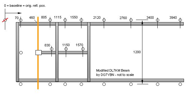
Positions zero is counting from original reflectos position as "0" on. The new reflectors are moved up front by 70 mm against their original position. Built DL7KM Beams can be adapted to the modification; the double booms spacing is with 1200 mm similar to the original design, as the Double Quad Loop is.
For the given below measures elements are of Ø 8 mm, Quad loops are Ø 5 mm. Due to the rectangular, loop style driver I suggest no SBC here. The common BC must meet the way your elements shall be fastened. Find BC numbers on my BC-page
An interesting detail is the D1 which is shorter than D2 and D3. This is not a typo in the table below. As well as all the parasitic elements seem quite short for a 144 MHz structure. Which is all due to the mutual coupling between the two largely understacked booms.
Update 2014-12-31, corr. length of D1
8 mm elements - upper and lower boom
       Refl.    DE       D1       D2       D3       D4       D5      D6      D7
Pos.   70       460      805      1115     1550     2120     2760    3400    3940 mm
Lgth.  1044      -       896      898      890      884      872     868     856  mm

8 mm elements - short center boom
       Refl.    DE       D1       D2       D3
Pos.   70       460      830      1150     1570 mm
Lgth.  1056      -       884      878      868  mm
Note: element lengths for Ø 8 mm fit 5/16" too
The Double Quads wire diameter is 5 mm. Circumfence of the loops and all measures identical with the original DL7KM Beam. Which are identical side lengths of 520 mm each, a total height of 1470 mm and a space of 20 mm at the centered feedpoint.
MNI tnx to Vladimir, UR5EAZ who sorted this website and .ez files for bugs and more
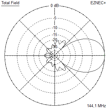
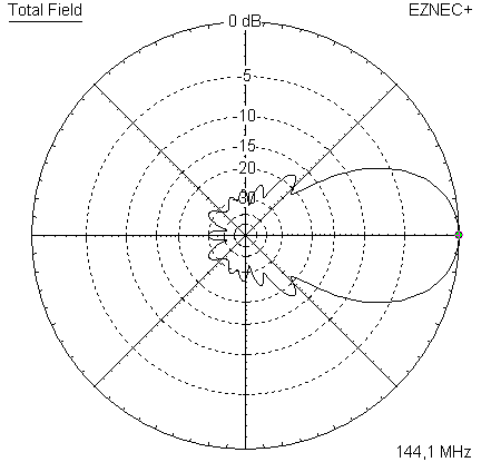
Pattern and VSWR Plots of the modified design
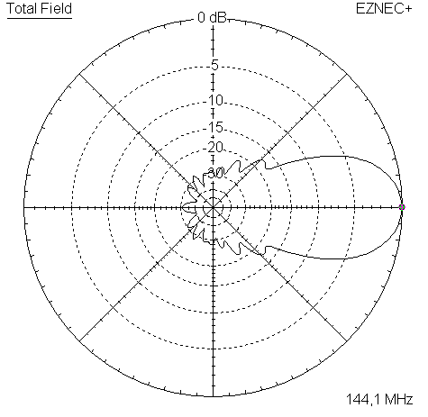
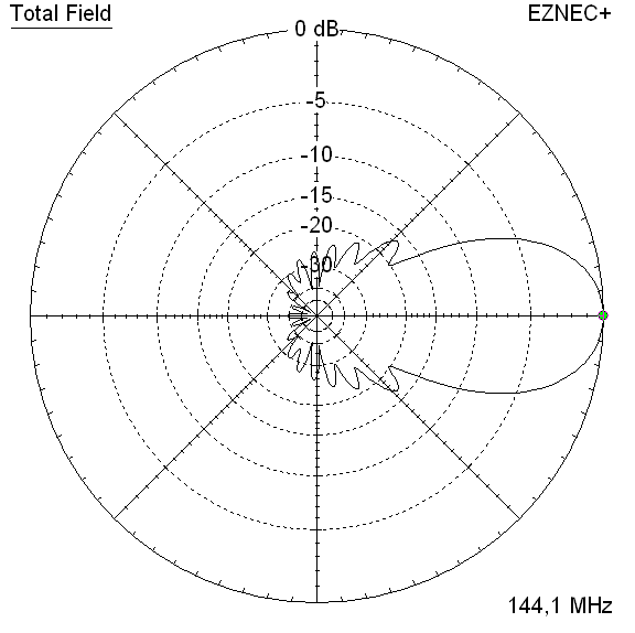
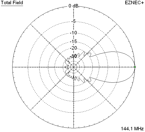
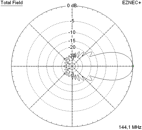
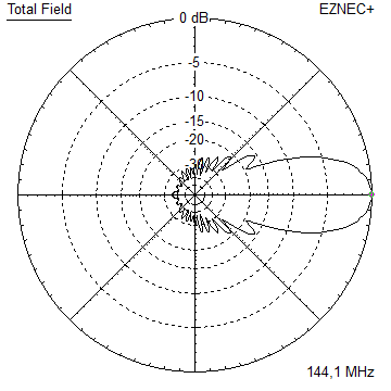
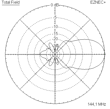
Elevation and Azimuth plot at 144.1 MHz

RL and SWR plot - simulated

Gain, F/B and F/R plot - simulated

Downloads
EZNEC file of the modified DL7KM Beam
Stacking the modified DL7KM Beam
Stacking Dist. DL6WU Formula
top-to-bottom (H-Plane) 3.61 m or 11.8 ft ✶
side-by-side (E-Plane) 3.25 m or 10.7 ft ✶
(✶) = for centre of antennas ie. in the middle point between the booms
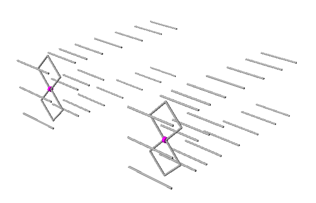
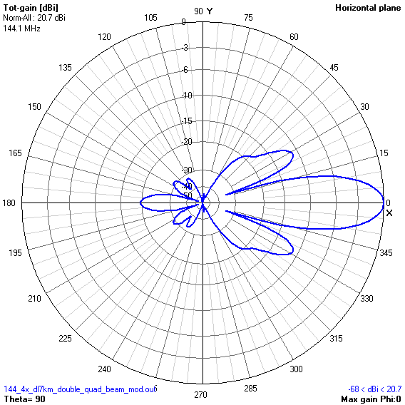
A 4 bay of modified DL7KM Beams at distances per DL6WU formula, gain = 20.7 dBi or 18.6 dBD
Note the unusual appearance of the stack. With the pattern being more wide in azimuth pattern the
used to view of a stacked Yagi bay is like reversed or tilted by 90 degrees here.
Explanation: Due to showing wider elevation patterns half power beam width (HPBW) angle than azimuth HPBW the ordinary 'single boom' Yagi is stacked with larger width than height. While the DL7KM beam is a '2 layer' stacked array in itself already. And the modified DL7KM beam shows 3 layers that bundle the pattern in elevation already. Hence we find a 'reverse' ratio of stacking width and height against what we know as common appearence of stacked single layer Yagis.
2 modified DL7KM Beams side-by-side, gain = 17.87 dBi or 15.72 dBD
3D pattern of 2 x modified DL7KM Beam side-by-side (4NEC2)

Modfied DL7KM Beam as a 4 Bay
Stacking Scheme


73, Hartmut, DG7YBN
