-
• Main Page
- • Home
• Antennas - • 144 MHz
- Straight Dipole
144 MHz YagisYBN 2-9m: 4.5 m moderate band width, low Antenna Temperature, good willing 50 ohms direct feed Yagi - a straight DE version twin to the GTV 2-9m
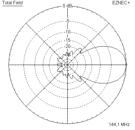
Elevation Plot
- GTV 2-2mA 50 ohms direct feed 2 ele. Yagi with bent DE and potential as broad beam Contest Stack.
It can be used as back-to-back stack:
- GTV 2-4w1.0 m 144-146 MHz wide band width version of the Low Noise Yagi with bent DE as useful for satellite operation as for contesting thanks to high F/B and small volume of rear quadrants lobs in general.
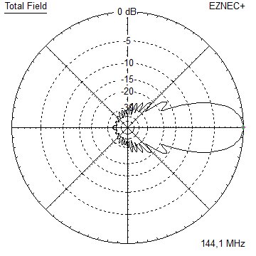
Elevation Plot at 144.1 MHz

- GTV 2-5m1.6 m moderate to wide band width version of the Low Noise Yagi with bent DE as useful for satellite operation as for contesting thanks to high F/B and small volume of rear quadrants lobs in general.
Elevation Plot

- GTV 2-6m2.4 m moderate band width version of the low impedance, yet 50 ohms direct feed Low Noise Yagi with bent DE introduced in Dubus 1/2013
Elevation Plot
- GTV 2-7w2.7 m wide band width version of the low impedance, yet 50 ohms direct feed Low Noise Yagi with bent DE introduced in Dubus 1/2013
Elevation Plot

- GTV 2-7n3.1 m narrow band, max. G/T version of the low impedance, yet 50 ohms direct feed Low Noise Yagi with bent DE introduced in Dubus 1/2013
Elevation Plot

- GTV 2-8w3.7 m wide-band, still good G/T and nice F/B version of the low impedance, yet 50 ohms direct feed Low Noise Yagi with bent DE introduced in Dubus 1/2013
Elevation Plot
- GTV 2-8n3.8 m narrow band, max. G/T version of the low impedance, yet 50 ohms direct feed Low Noise Yagi with bent DE introduced in Dubus 1/2013
Elevation Plot
- GTV 2-9n4.3 m narrow band, balanced between low Antenna Temp. and G/T version of the low impedance, yet 50 ohms direct feed Low Noise Yagi with bent DE introduced in Dubus 1/2013
Elevation Plot

- GTV 2-9m4.5 m moderate band width, low Antenna Temp. version of the low impedance, yet 50 ohms direct feed Low Noise Yagi with bent DE introduced in Dubus 1/2013
Elevation Plot
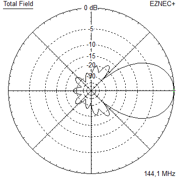
- GTV 2-10LT5.1 m moderate band width, lowest Antenna Temp. version of the low impedance, yet 50 ohms direct feed Low Noise Yagi with bent DE introduced in Dubus 1/2013
Elevation Plot
- GTV 2-11LT6.0 m moderate band width, lowest Antenna Temp. version of the low impedance, yet 50 ohms direct feed Low Noise Yagi with bent DE introduced in Dubus 1/2013
Elevation Plot
- GTV 2-12m mk2Improved 6.8 m version of the low impedance, yet 50 ohms direct feed Low Noise Yagi with bent DE introduced in Dubus 1/2013
Elevation Plot:
- GTV 2-12n6.8 m narrow band version of the low impedance, yet 50 ohms direct feed Low Noise Yagi with bent DE introduced in Dubus 1/2013
Elevation Plot:
- GTV 2-13m7.5 m version of the low impedance, yet 50 ohms direct feed Low Noise Yagi with bent DE introduced in Dubus 1/2013
Elevation Plot:

- GTV 2-14w8.4 m version of the low impedance, yet 50 ohms direct feed Low Noise Yagi with bent DE introduced in Dubus 1/2013
Elevation Plot
- GTV 2-16w10 m version of the low impedance, yet 50 ohms direct feed Low Noise Yagi with bent DE introduced in Dubus 1/2013
Elevation Plot
- GTV 2-18w11.7 m version of the low impedance, yet 50 ohms direct feed Low Noise Yagi with bent DE introduced in Dubus 1/2013
Elevation Plot
- GTV 2-19m12.4 m version of the low impedance, yet 50 ohms direct feed Low Noise Yagi with bent DE introduced in Dubus 1/2013
Elevation Plot
- Straight Dipole
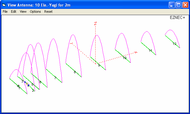
GTV 2-10 LT Yagi with bent Driven Element
EME + SSB Low Temperature Version
This Yagi has quite a low Antenna Temperature and a moderate gain for its length, which altogether is leading to a
good G/T number. It may serve as a contest stack or medium size EME 4-Yagi-Bay, especially under tough RXing
conditions.The bent DE (K6STI style) transforms to 50 ohms at feed point for direct feed.
Find details on this Yagi in
• xpol configuration including SM5BSZ BC element cutting table
• with bent folded dipole
further down.
A GTV 2-10LT built by F5UBZ

Loic, F5UBZ reports "Hello, for info: I made gtv 2-10 LT antenna using your dimensions design (25 x 25 mm boom),
first impression is very impressive. ... dipole box was made using a very nice box available at Conrad (Wiska COMBI 206)".
A GTV 2-10LT built by I3QJZ

A GTV 2-10LT built by DL2VL

Chasing the famous and slightly longer EF0210LT by YU7EF .... . Using DL6WU formula derived stacking distances
the GTV 2-10 produces just 2.9 K higher Antenna Temperature but better G/T and F/R. When "under stacked" at
only 95 % of DL6WU distances it produces a lower T_ant and still better G/T, see table below:
(Note: this is not the official VE7BQH G/T table; the GTV2-10 is not listed in there yet)

Performance Data
                     Elem. 4 mm     Elem. 8 mm

Gain vs. isotr. Rad.  14.4 dBi       14.5 dBi
Gain vs. Dipole       12.3 dBD       12.3 dBD
-3 dB E-plane         36.4 deg.      36.2 deg.
-3 dB H-plane         40.0 deg.      40.0 deg.
F/B                  -30.1 dB       -30.1 dB
F/R                  -26.3 dB       -26.5 dB
Impedance               50 ohms        =
Mechan. Length        5064 mm          =
Electr. Length        2.44 λ           =

Stacking Dist. h-pol.
top-to-bottom         3.04 m
side-by-side          3.35 m
Geometry

Metric Measures Versions for On-Boom-Insulators
Table 1: This Yagi with 8 mm elements on a 20 x 20 mm boom with standard insulators
|
Ele. 8.0 mm DE 10 mm Boom 20 x 20 mm |
|

"Ready to saw and drill" data for mounting elements on boom with BC according DG7YBN for standard insulators as sold by HF Kits NL, WiMo, 7arrays:
Includes an SBC of 2.3 mm

Note: Element lengths for Ø 8 mm fit 5/16" too
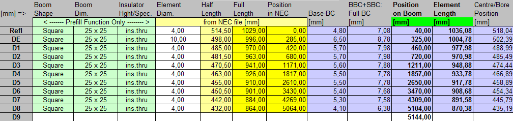
Table 2: This Yagi with 8 mm elements on a 25 x 25 mm boom with standard insulators
|
|
Ele. 8.0 mm DE 10 mm Boom 25 x 25 mm |
|

"Ready to saw and drill" data for mounting elements on boom with BC according DG7YBN for standard insulators as sold by HF Kits NL, WiMo, 7arrays:
Includes an SBC of 2.3 mm

Note: Element lengths for Ø 8 mm fit 5/16" too
Imperial Measures Versions for mounting elements through boom
"Ready to saw and drill" data for mounting elements through boom with BC according SM5BSZ's BC.exe:
Note: with through Boom BC it is important to stick to the boom end offsets given below!
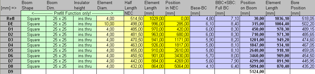
Table 1: 4.76 mm = 3/16 inch El., Imperial Boom 1 x 1 x 1/16 inch and Metric 25 x 25 x 1.6 mm
|
Boom shape: square Boom dim: 1 x 1 inch and 25 x 25 mm Wall thickn.: 1.6 mm = 1/16 in Holes in boom: 7.5 mm Offset rear: 40 mm Offset front: 40 mm |

This includes an SCB of 2.3 mm.
Metric Measures Versions for mounting elements through boom
"Ready to saw and drill" data for mounting elements through boom with BC according SM5BSZ's BC.exe:
Note: with through Boom BC it is important to stick to the boom end offsets given below!
Table 1: 4.00mm El., Metric Boom 25 x 25 x 2 mm
|
Boom shape: square Boom dim: 25 x 25 mm Wall thickn.: 2.0 mm Holes in boom: 6.9m Offset rear: 40 mm Offset front: 40 mm |
This includes an SCB of 2.3 mm.
Bent Dipole
The Drivers diameter is 10 mm for all examples.
Use EZNEC's Auto-Segmentation at 380 MHz.
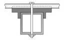
Sketch of Driver Cell

• Bent DE Online Calculator web app
Pattern and VSWR Plots
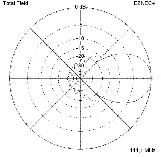
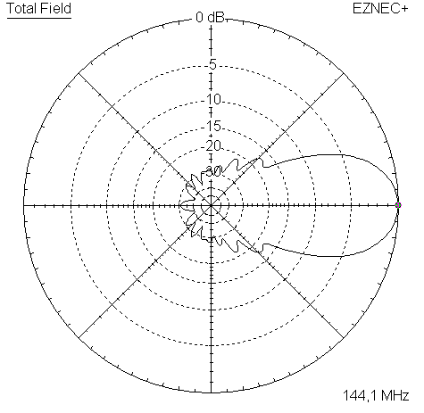
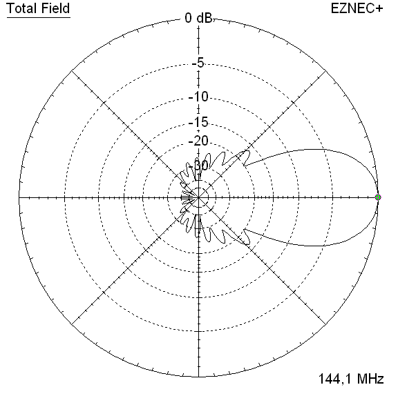
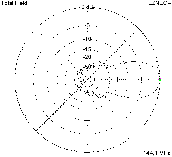
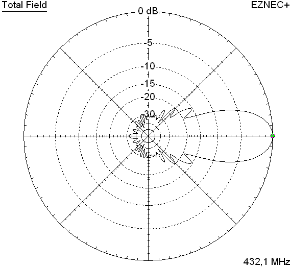
Elevation and Azimuth plot at 144.1 MHz


RL and SWR plot - simulated

Return Loss plot by DL2VL:
Jörg reports best VSWR ie. Return Loss was more towards 144.2 before he shorted the Driven Element a little too far

Return Loss S11 (dB) simulated over a span of 120 - 160 MHz
|
|

and calibrated measurement lines, by ZS6JON

Downloads
EZNEC file of this Yagi with 8 mm elem.
EZNEC file of this Yagi with 4 mm elem.
EZNEC file of this Yagi with 4 mm elem. and Folded Dipole
200 ohms version with Folded Dipole
Right when I introduced the GT Yagi series I have shown that its possible to swap straight split dipoles with folded dipoles
for any bent Driver Yagi (s. '144/432 MHz Long Yagis with a bent Driven Element' Dubus 1/2013 & Dubus Technik XII).
The bent dipole delivers 50 ohms as straigth dipole and 200 ohms in its folded form; just as with any non-bent dipole.
Use a λ/2 balun as with any other folded dipole, see here
Here is the GTV 2-10LT using a Folded Dipole that is close to DJ9BV BVO 2 m Yagis Version:
Outer straight Length = 990 mm, inner height = 50 mm, tubes Ø = 8 x 1 mm.
Attention:
Using a complete DJ9BV Folded Dipole with balun cut using v-factor only will not work out ending
up at 144.3 MHz but around 143.9 MHz. At least the half wave balun must be measured & cut to act as a quarter wave
stub while testing on half frequency of the foreseen i.e. 72.2 MHz for the 2 m band.

Making it a build for the experienced maker that has a VNA.
Bent tips rearbound by 30 mm, each a 100 mm from mid of boom on ... and insert.

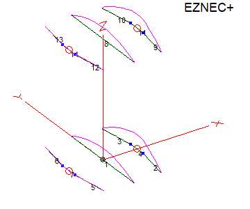
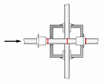
Cross Yagi / X-Pol
on boom 25 x 25 mm with elements through boom
Simulated DE offset of 16 mm for mounting a straight split DE below or on top of the 25 mm boom in a narrow plastic case
Elements are of diameter 4 mm, so the DJ9BV nylon rivet methode can be uses to mount elements insulated through boom.
on boom offset: second (vertical plane) = 550 mm

Element table for building with the advanced SM5BSZ BC applied on 25 x 25 x 2.5 mm boom, 6 mm holes in boom for nylon rivets.
Offset on both ends is 30 mm
Element table for building with the advanced SM5BSZ BC applied on 20 x 20 x 2.0 mm boom, 6 mm holes in boom for nylon rivets.
Offset on both ends is 30 mm

Mounting elements with funiture hole plugs from the Do-It-Yourself market (LDPE). Drill holes of 3.9 mm for 4 mm elements.
This will also work with thicker diameters as 5, 6 or 8 mm. But BC and element lengths needs to be adapted via my MS Excel
Yagi Element Configuration Tool, see here

This Yagi as XPOL: 4.76 mm elements through a 1 x 1 inch boom:
"Ready to saw and drill" data for mounting elements through boom with BC according SM5BSZ's BC.exe:
Note: with through Boom BC it is important to stick to the boom end offsets given below!
For Elements 3/16 inch through a 1 x 1 inch boom
This table is only valid for:
Boom shape: square
Boom dim: 1 x 1 in
Wall thickn.: 1/16 in
Holes in boom: 7.5 mm
Offset rear: 40 mm resp. 590 mm
Offset front: 590 mm resp. 40 mm
Note: This includes a "Segmentation Density Correction" (SBC) of 2.3 mm
Read abt. the SBC here
![]()
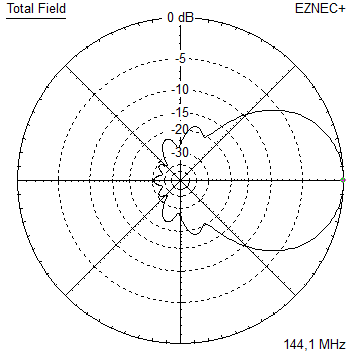
Performance Data, single (horiz.) polarisation)
Gain vs. isotr. Rad.  14.42 dBi
Gain vs. Dipole       12.3 dBD
-3 dB H-plane         40.0 deg.
-3 dB E-plane         36.2 deg.
F/B                  -30.0 dB
F/R                  -25.3 dB
Impedance               50 ohms
VSWR Band Width     1.34:1 *
Mechan. Length        5614 mm

Stacking Dist.
top-to-bottom         3.19 m
side-by-side          3.19 m

*) as in VE7BQH G/T table = at 145.00 MHz
| Pattern plot, hor. pol. only | SWR plane 1 | and SWR plane 2 |

|

|

|
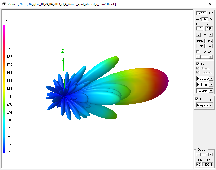
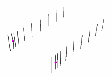
Simulation of an array of 8 GTV 2-10LT xpol
Stacking distances:
hor. average of DL6WU in h/v = 3195 mm side-by-side
vert. DL6WU minus 200 mm for decrease of 1st and second lobe 2995 mm.


Stacking
Stacking Dist.    DL6WU Formula
H-plane               3.35 m
E-plane               3.04 m
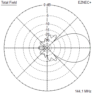
Data of 2 Yagi stack using DL6WU stacking distances
an "urban" low noise solution: two times GTV2-10LT vertically polarised;
just a 3 m aluminum rod and a Yaesu G5500 azim./elev.-rotor combination or similar will do for digital EME
Gain vs. isotr. Rad.  17.4 dBi
Gain vs. Dipole       15.3 dBD
F/B                  -31.3 dB
F/R                  -28.5 dB
T_ant                219.5 K*
G/T                  -6.02 dB*
Theoretical numbers, no phasing line losses
nor imperfections caused by H-frame included
*) T_sky = 200 K, T_earth = 1000 K as in VE7BQH G/T table
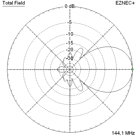
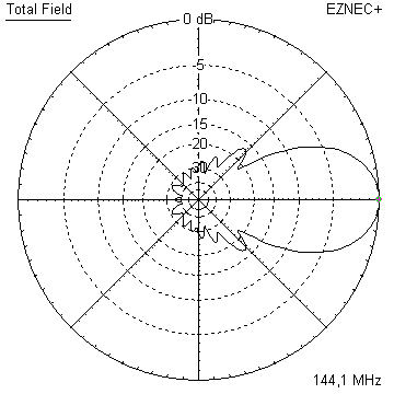
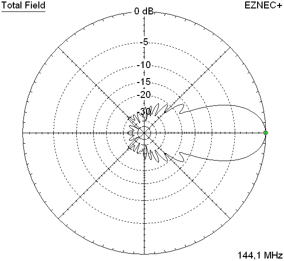
Elevation and azimuth plot and data of 4 Yagi bay using DL6WU stacking distances


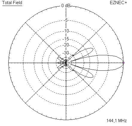
Gain vs. isotr. Rad.  20.4 dBi
Gain vs. Dipole       18.2 dBD
-3 dB H-plane         16.2 deg.
-3 dB E-plane,        18.0 deg.
F/B                  -32.6 dB
F/R                  -29.7 dB
T_ant                227.7 K*
G/T                  -3.18 dB*
Theoretical numbers, no phasing line losses
nor imperfections caused by H-frame included
*) T_sky = 200 K, T_earth = 1000 K as in VE7BQH G/T table
73, Hartmut, DG7YBN