-
• Main Page
- • Home
• Antennas - • 144 MHz
- Straight Dipole
144 MHz YagisYBN 2-9m: 4.5 m moderate band width, low Antenna Temperature, good willing 50 ohms direct feed Yagi - a straight DE version twin to the GTV 2-9m
Elevation Plot
- GTV 2-2mA 50 ohms direct feed 2 ele. Yagi with bent DE and potential as broad beam Contest Stack.
It can be used as back-to-back stack:
- GTV 2-4w1.0 m 144-146 MHz wide band width version of the Low Noise Yagi with bent DE as useful for satellite operation as for contesting thanks to high F/B and small volume of rear quadrants lobs in general.
Elevation Plot at 144.1 MHz

- GTV 2-5m1.6 m moderate to wide band width version of the Low Noise Yagi with bent DE as useful for satellite operation as for contesting thanks to high F/B and small volume of rear quadrants lobs in general.
Elevation Plot

- GTV 2-6m2.4 m moderate band width version of the low impedance, yet 50 ohms direct feed Low Noise Yagi with bent DE introduced in Dubus 1/2013
Elevation Plot
- GTV 2-7w2.7 m wide band width version of the low impedance, yet 50 ohms direct feed Low Noise Yagi with bent DE introduced in Dubus 1/2013
Elevation Plot

- GTV 2-7n3.1 m narrow band, max. G/T version of the low impedance, yet 50 ohms direct feed Low Noise Yagi with bent DE introduced in Dubus 1/2013
Elevation Plot

- GTV 2-8w3.7 m wide-band, still good G/T and nice F/B version of the low impedance, yet 50 ohms direct feed Low Noise Yagi with bent DE introduced in Dubus 1/2013
Elevation Plot
- GTV 2-8n3.8 m narrow band, max. G/T version of the low impedance, yet 50 ohms direct feed Low Noise Yagi with bent DE introduced in Dubus 1/2013
Elevation Plot
- GTV 2-9n4.3 m narrow band, balanced between low Antenna Temp. and G/T version of the low impedance, yet 50 ohms direct feed Low Noise Yagi with bent DE introduced in Dubus 1/2013
Elevation Plot

- GTV 2-9m4.5 m moderate band width, low Antenna Temp. version of the low impedance, yet 50 ohms direct feed Low Noise Yagi with bent DE introduced in Dubus 1/2013
Elevation Plot
- GTV 2-10LT5.1 m moderate band width, lowest Antenna Temp. version of the low impedance, yet 50 ohms direct feed Low Noise Yagi with bent DE introduced in Dubus 1/2013
Elevation Plot
- GTV 2-11LT6.0 m moderate band width, lowest Antenna Temp. version of the low impedance, yet 50 ohms direct feed Low Noise Yagi with bent DE introduced in Dubus 1/2013
Elevation Plot
- GTV 2-12m mk2Improved 6.8 m version of the low impedance, yet 50 ohms direct feed Low Noise Yagi with bent DE introduced in Dubus 1/2013
Elevation Plot:
- GTV 2-12n6.8 m narrow band version of the low impedance, yet 50 ohms direct feed Low Noise Yagi with bent DE introduced in Dubus 1/2013
Elevation Plot:
- GTV 2-13m7.5 m version of the low impedance, yet 50 ohms direct feed Low Noise Yagi with bent DE introduced in Dubus 1/2013
Elevation Plot:

- GTV 2-14w8.4 m version of the low impedance, yet 50 ohms direct feed Low Noise Yagi with bent DE introduced in Dubus 1/2013
Elevation Plot
- GTV 2-16w10 m version of the low impedance, yet 50 ohms direct feed Low Noise Yagi with bent DE introduced in Dubus 1/2013
Elevation Plot
- GTV 2-18w11.7 m version of the low impedance, yet 50 ohms direct feed Low Noise Yagi with bent DE introduced in Dubus 1/2013
Elevation Plot
- GTV 2-19m12.4 m version of the low impedance, yet 50 ohms direct feed Low Noise Yagi with bent DE introduced in Dubus 1/2013
Elevation Plot
- Straight Dipole


GTV 2-12n Yagi with bent Driven Element
EME + SSB narrow band version
This Yagi has very low back lobes for its length. It may serve as single antenna for Tropo, MS and top performing for EME
or make a quiet contest antenna due to its high F/B. The bent DE (K6STI style) transforms from approx. 28 ohms to 50 ohms at feed point.
A narrow band version of the GTV that needs skills and precision when building it, but will reward with neat properities in return.
WARNING: You probably should avoid building this Yagi as
Expert John, G4SWX sees me in the dark ages antenna wise.

"I suspect that Goran has been doing this on many of his designs whereas DG7YBN seems to be in the dark ages..........
There is no set recipe for this stuff. Building a world-class array for 144MHz EME does not come from following any website recipe but
only from exercising good engineering principles all through the design and build.
I still see many on 144MHz EME who are sadly 6+dB from where they should be."
No proof, no simulation, no attempt to contact me forehand. What looks funny and is, is in a way sad and rude.
In a way it is even sader, that the Moon-Net community takes such statements uncommented.
BTW: The answer to varying h-/v-plane element offset in xpol-Yagis?
This offset has not in the least to do with pattern shape nor primary isolation between the planes.
That is only down to stricly 90 degrees between them. So why do some designer have the planes
at 520, 200, 120 mm or an seemingly abitrary distance? Near 520 mm is a cheap guess:
Two feedlines of equal length provide circular polarisation (CP). For all other distance one of the
feed/phasing lines must be of a different length for CP. See my calculator on dg7ybn.de/Building/xpol.htm
Q: So why are these distances?
A: Mostly because this way the element sets show greatest distance of individual elements,
which is best for least mutual coupling if elements are tight to say 20 mm while still
fitting a given boom length. Especially DE and D1 of both planes shall be nicely separated.
Rightly praised for his works Goran knows that, hence we see a 205mm equal to 35.5 degrees at 144 MHz
in his design in the thread (would he ever compromise on Yagi performance?) and I do similar.
... Time gap closed ...
Though being a narrow band design it obviously provides a stable SWR so that even the Crossyagi or "xpol" built is managable without much
challenges. One can imagine from the very deep dip in the simulated (-60 dB) and measured Return Loss that this design "rests in its center
frequency position",see the confirming feedback below:
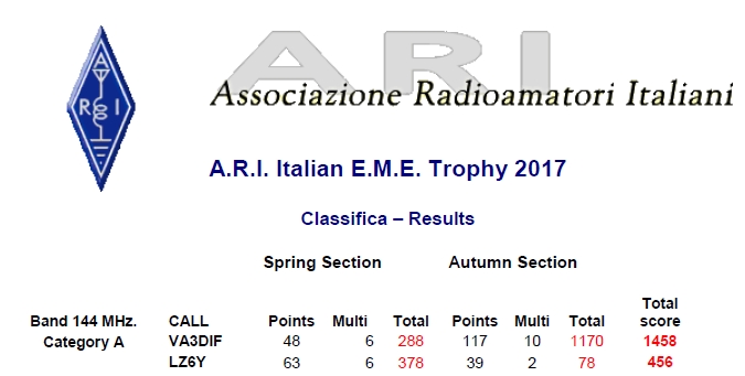
Congrats: Ian, VA3DIF wins 2017 ARI EME Tropy category A (under 4 wl antenna) with a GTV 12-2n
Some more feedback:
A 4 bay of GTV 2-12n xpol built by John, ZS6JON Oct. 09th 2016


"Well, all I can say is that they blew me away. Just as you predicted. Everything has changed. My Noise levels are lower. I have less Birdies. Screen is clearer. I used to get bad lines across Map 65 when elevating ... now nothing. Today I switched on again as there is an expedition on. They signals are just amazing. I have never seen anything like it. Even Alex, ZS6EME logged into my PC via Teamviewer and couldn’t believe it. His first comment was ... 'what happened to all your Noise?'.
The signals are amazing Hartmut. A new world for me. Not only on RX but TX as well. When I started calling I got Whatsapp and emails asking 'What the xxxx are you using? Never heard you so strong.'"
ZS6JON used 4 x 20 element DJ9BV xpol Yagis and I3DLI 4 x 9 ele. hor. pol. & 4 x 6 ele. vert. pol. before. I wish to add, that the tribute is not mine solely but also goes to SM5BSZ for his obviously very sound BC.exe

Slideshow: GTV 2-12n xpol by John, ZS6JON
Return Loss, h-pol and v-pol, feed point and more
How many prolific VHF Operators have looked up this website since the ZS6JON array notes have been pubished?
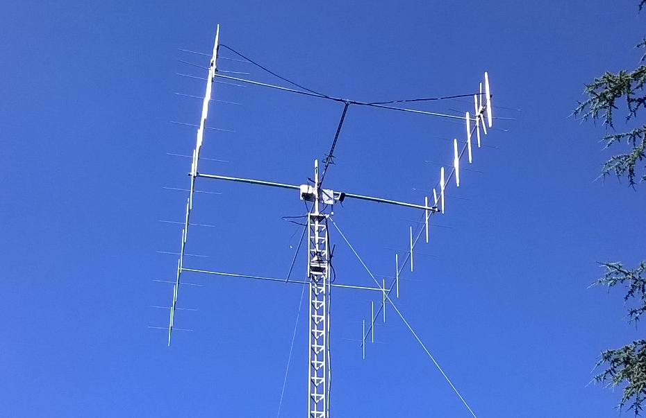
GTV 2-12n built by Niels, G8RWG
This Yagi is built with elements 4.00 mm insulated through a 1 x 1 inch boom.
Niels reports "Each leg of DE was 4mm shorter than calculation and drawback is 40mm - calculation was 59mm."
Using a 1/4 wl line from 410 mm including the connector of LMR 400 UF, which s plotted at 144.28 MHz.
> G8RWG got 7th place in the 2022 ARRL EME Contest with this array and an Italab SSPA.
4 x GTV 2-12n xpol by G8RWG (click to enlarge):


H-POL - DE length 994 mm tip to tip, distance (of tips) to reflector 215 mm.
V-POL - DE length 973 mm tip to tip, distance (of tips) to reflector 200 mm.
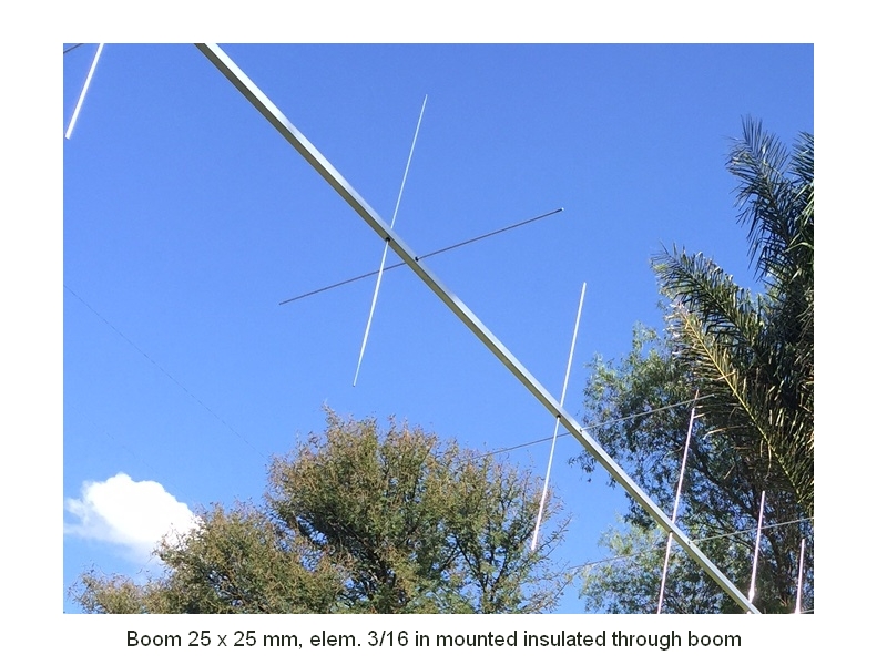
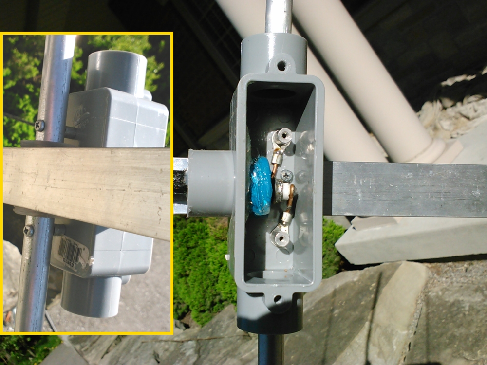
GTV 2-12n built by Ian, VA3DIF / G7ORZ / YO3DIF
This Yagi is built with elements 4.76 mm or 3/16 inch insulated through a 1 x 1 inch boom
Click on images to enlarge
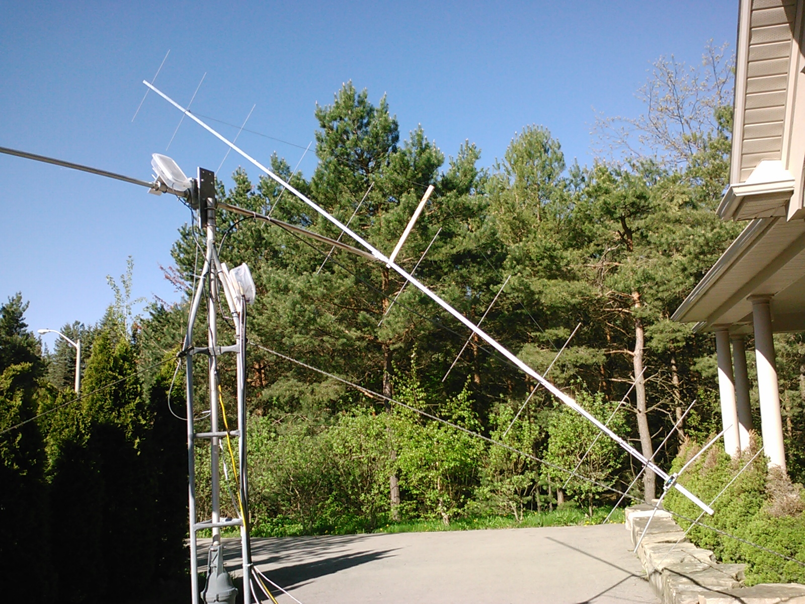

"Finally I did it !!! I have an antenna with spot on SWR at your choice from SSB to FM. Resonance can be moved from 145,5 all the way to 143.55 and back with no problems. There is only ONE deep resonance…so is ideal for EME. Today Monday was a great day on the Moon with Rx reports up to -11db. Something new for me I started to decode QSOs at -30dB and worked my first single Yagi station with also 400W and some ground effect there .
Congratulations for a great design !!! 73 Ian"
He adds: "The whole trick was D1 which acts like tuning knob"
Here is a video of a 150 W EME QSO between VA3DIF and KK6FAH:
it is done by KK6FAH and uploaded on his Dropbox for Download 98 MB, here
VA3DIF used 150 W in shack only, single GTV 2-12n in low position, LNA homebrew PG 103 +,
KK6FAH has a 3 x 13 elem. LFA stacked in a triangle with fully rotatable boom axes he calls
TARP (Triangular Array Rotatable Polarity) which is described in Dubus 4/2016.
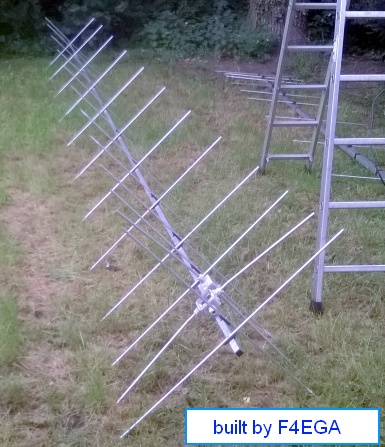
2 x GTV 2-12n xpol built by Patrick, F4EGA using 20x20 mm boom and 8 mm elements:
GTV 2-12n built by Roberto, I3QJZ


A review on circumstances when making this design
The GTV 2-12n current profile can not deny a close relation to the YU7EF way to design here. But instead of replicating the YU7EF designs
this model is an independant forward development due to quite different radiation pattern, element lengths on booms mid section,
positions and produced G/T numbers. Please note that unlike pubished by DK7ZB I do not "use the YU7EF Director-chain", just some of my designs
are influenced by his way to design. Or do my patterns look like EFxxxx designs at all? There is a line between replicating and following
shared prime design goals. For more on the history of bent DE Long Yagi designs see here
Discussion: Much of the up and down of gain and thus G/T in the clipping of the G/T Table below is due to bandwidth. Surely I gained G/T on cost
of some bandwidth here. But look up the GTV2-12m mk2's numbers. That design is more OWA style and thus of higher bandwidth with still about
same G/T as the DK7ZB-modified-Driver EF0212B if we extrapolate on electrical length and to be expected gain. Looking at the 12 ele. G0KSC LFA
in the context of G/T and bandwidth it is an excellent antenna.
When DK7ZB first introduced the replicated EF0212B of YU7EF with exchanged Driver in Sept. 2013 he indicated it a design study but
labeled it as DK7ZB-12-50-V "Ultra-Low Noise optimized 50-Ohm-12-El.-V-Yagi" which strongly deduced an own design.
See to how DK7ZB marvels at YU7EF's works today. Lets not forget that it was quite the opposite way for years.
Though being a bit shorter the GTV 2-12n tops the G/T of the DK7ZB Design Study with ease.
Please remember that Low Antenna Temperature is essential but that it is the G/T number that counts if we design for Low Noise objectives
Here is a clipping of the official 144 MHz G/T Table.
The DK7ZB 12 (red row) in fact is an YU7EF EF0212B with bent Driver as I produced it from the K6STI version.

|

|
Performance Data
Gain vs. isotr. Rad.  15.68 dBi
Gain vs. Dipole       13.53 dBD
-3 dB E-plane         31.6  deg.
-3 dB H-plane         34.0  deg.
F/B                  -39.4  dB
F/R                  -25.7  dB
Impedance               50  ohms
Mechan. Length        6874  mm
Electr. Length        3.30  λ

VSWR at 144.500       1.49 [/]

Stacking Dist. h-pol.    DL6WU     max. G/T
top-to-bottom           3.56 m      3.74 m
side-by-side            3.82 m      4.20 m
Geometry

Ø8 mm Elements - On Boom - Dimensions (BC acc. DG7YBN)
		Refl	 DE(b)	 DE(a)	D1	D2	D3	D4	D5	D6	D7	D8	D9	D10
Pos. 		0	 184	 243	428	780	1323	1968	2719	3542	4394	5284	6139	6874
Boom 20x20 mm	1014.2	(958.2)	(100)	954.2	947.2	924.2	908.2	897.2	886.2	875.2	870.2	863.2	840.2
Boom 25x2 5mm	1017.9	(961.9)	(100)	957.9	950.9	927.9	911.9	900.9	889.9	878.9	873.9	866.9	843.9
Ø8 mm Elements - On Boom with Stauff Clamps - provisional Dimensions: only SBC + 0.5 resp. 0.7 mm added here
		Refl	 DE(b)	 DE(a)	D1	D2	D3	D4	D5	D6	D7	D8	D9	D10
Pos. 		0	 184	 243	428	780	1323	1968	2719	3542	4394	5284	6139	6874
Boom 25x25 mm	1010.8	(954.8)	(100)	950.8	943.8	920.8	904.8	893.8	882.8	871.8	866.8	859.8	836.8
Boom 1x1 inch	1011.0	(955.0)	(100)	951.0	944.0	921.0	905.0	894.0	883.0	872.0	867.0	860.0	837.0
Ø6 mm Elements insulated through Boom - Dimensions (BC acc. SM5BSZ)
		Refl	 DE(b)	 DE(a)	D1	D2	D3	D4	D5	D6	D7	D8	D9	D10
Pos. 		0	 184	 243	428	780	1323	1968	2719	3542	4394	5284	6139	6874
Boom 30x30 mm	1019.1	(961.9)	(100)	964.4	958.0	936.4	919.3	910.2	899.2	888.1	884.1	877.0	852.8
Ø4.76 mm Elements insulated through Boom - Dimensions (BC acc. SM5BSZ)
Boom 25x25 mm or 1 x 1 in, see xpol details further down the page, chose one plane only,
BUT leave the boom at length or ask for a recalcuclaton!
This Yagi with 3/16 inch elements (EZNEC Auto Segmentation @ 380 MHz)

Note: to minimise pattern distortion resulting from DE offset when using the 30 mm boom with ele. though boom the DE
should be insulated passed through boom in ele. plane here and be feed from either side of boom.
The SBC = (144.60 MHz - 144.20 MHz) x 5.85 mm/MHz = 2.3 mm is included
in all of the above numbers so that these all are ready to build measures.
Note: element lengths for Ř 8 mm fit 5/16" too
• For details on the On-Boom BC see here
• For details on DE and BC on it see here
• Bent DE Online Calculator as web app
Ø 3/16 inch Elements - Through Boom - Dimensions (BC acc. SM5BSZ's BC.exe)
"Ready to saw and drill" data for mounting elements through boom with BC according SM5BSZ's BC.exe:
This table is only valid for:
Boom shape: square
Boom dim: 1 x 1 in
Wall thickn.: 3.25 mm
Holes in boom: 7.8 mm
Offset rear: 40 mm
Offset front: 40 mm
Note:
This does include an SBC of 2.28 mm
![]()
Ø 1/4 inch Elements, 3/8 inch Dipole - Through Boom - Dimensions (BC acc. SM5BSZ's BC.exe)
"Ready to saw and drill" data for mounting elements through boom with BC according SM5BSZ's BC.exe:
This table is only valid for:
Boom shape: square
Boom dim: 1 x 1 in
Wall thickn.: 1.6 mm
Holes in boom: 8.5 mm
Offset rear: 40 mm
Offset front: 40 mm
Note:
This does include an SBC of 2.28 mm
![]()
Bent Dipole

Pattern and VSWR Plots
Elevation and Azimuth plot at 144.1 MHz


SWR and Return Loss plots - simulated with 4nec2
Return Loss plot in xpol configuration taken by F4EGA with a miniVNA, tnx Patrick!
Built on 20 x 20 mm boom with 8 mm elements on boom and insulators from Nuxcom. With my BC and SBC applied as given in table above.

X-pol Details
Below: Current distribution feeding h-pol only. The pattern is unspoiled by the x-configuration in simulation) though some
degradation will occure on real builds due to introducing feeding coaxes, dipole boxes, boom and mast clamps etc. as on every x-pol Yagi.

|
|
xpol builders table 1: GTV 2-12n, 3/16 inch elements through boom:
"Ready to saw and drill" data for mounting elements through boom with BC according SM5BSZ's BC.exe:
Note: with through Boom BC it is important to stick to the boom end offsets given below!
This table is only valid for:
Boom shape: square
Boom dim: 25 x 25 mm
Wall thickn.: 2.0 mm
Holes in boom: 7.5 mm
Offset rear: 40 mm resp. 132 mm
Offset front: 132 mm resp. 40 mm
Note: This includes a "Segmentation Density Correction" (SBC) of 2.3 mm
Read abt. the SBC here
Elements in h-plane

Offset in x (boom positions) of h-pol to v-pol plane is 92.5 mm
xpol builders table 2: GTV 2-12n, 4.0 mm elements through a 25 x 25 mm boom:
"Ready to saw and drill" data for mounting elements through boom with BC according SM5BSZ's BC.exe:
Note: with through Boom BC it is important to stick to the boom end offsets given below!
|
This table is only valid for: Boom shape: square Boom dim: 25 x 25 mm Wall thickn.: 2.0 mm Holes in boom: 6.0 mm Offset rear: 40 mm resp. 132 mm Offset front: 132 mm resp. 40 mm |
|

Note: This includes a "Segmentation Density Correction" (SBC) of 2.3 mm
Read abt. the SBC here
Elements in h-plane


Offset in x (boom positions) of h-pol to v-pol plane is 92.5 mm
xpol builders table 3: GTV 2-12n, 4.0 mm elements through a 1 x 1 inch boom:
"Ready to saw and drill" data for mounting elements through boom with BC according SM5BSZ's BC.exe:
Note: with through Boom BC it is important to stick to the boom end offsets given below!
|
This table is only valid for: Boom shape: square Boom dim: 1 x 1 in Wall thickn.: 1/16 or 0.063 inch or 1.6 mm Holes in boom: 6.0 mm Offset rear: 40 mm resp. 132 mm Offset front: 132 mm resp. 40 mm |
|
Note: This includes a "Segmentation Density Correction" (SBC) of 2.3 mm
Read abt. the SBC here
Elements in h-plane
![]()
![]()
Offset in x (boom positions) of h-pol to v-pol plane is 92.5 mm
Downloads
EZNEC file of this Yagi with 8 mm elements
Stacking
3Dim. plot of a 4 Yagi bay using DL6WU stacking distances

Stacking Dist.    DL6WU Formula    max. G/T
H-plane               3.56 m        3.74 m
E-plane               3.82 m        4.20 m
Elevation plot and data of 4 Yagi bay using DL6WU stacking distances

Gain vs. isotr. Rad.  21.60 dBi
Gain vs. Dipole       19.45 dBD

F/B                  -35.5 dB
F/R                  -29.0 dB
T_ant                220.4 K*
G/T                  -1.83 dB*

Theoretical numbers, no phasing line losses
nor imperfections caused by H-frame included
*) T_sky = 200 K, T_earth = 1000 K as in VE7BQH G/T table
Data of 4 Yagi bay using distances for max. G/T
Gain vs. isotr. Rad.  21.71 dBi
Gain vs. Dipole       19.56 dBD

F/B                  -36.0 dB
F/R                  -26.4 dB
T_ant                223.5 K*
G/T                  -1.78 dB*
Theoretical numbers, no phasing line losses
nor imperfections caused by H-frame included
*) T_sky = 200 K, T_earth = 1000 K as in VE7BQH G/T table
73, Hartmut, DG7YBN