-
• Main Page
- • Home
• Antennas - • 144 MHz
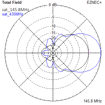
- YBN 3+7 SATA Satellite Yagi with 3 ele. for 145 MHz + 7 ele. for 435 MHz for handheld use
Elevation Plots
- YBN 2-2wA 50 ohms direct feed 2 ele. Yagi with high potential as broad beam Contest Stack.
See yourself and compare to DJ9HO Double Quads and 7ZB Oblongs. Full details on 2 and 4 Yagi stacks are given
3D Pattern of 4 x Stack

- YBN 2-5m (5-8)1.6 m high F/R, good willing 50 ohms direct feed Yagi as introduced as short version of the 5-8 in Dubus 4/2012
Elevation Plot
- YBN 2-8m (5-8)3.6 m nice G/T, good willing 50 ohms direct feed Yagi as introduced as expanded version of the 5-8 in Dubus 4/2012
Actually it seems to be so good that DK7ZB decided to use it as draft for the 8 ele. OWM he just published.
Elevation Plot
- YBN 2-9m4.5 m moderate band width, low Antenna Temperature, good willing 50 ohms direct feed Yagi - a straigh DE version twin to the GTV 2-9m
Elevation Plot
- YBN 2-10w (5-8)5 m wide band, good willing 50 ohms direct feed Yagi as introduced with straight DE expanded version of the 5-8 in Dubus 4/2012
Elevation Plot

- GTV 2-6m2.4 m moderate band width version of the low impedance, yet 50 ohms direct feed Low Noise Yagi with bent DE introduced in Dubus 1/2013
Elevation Plot
- GTV 2-7n3.1 m narrow band, max. G/T version of the low impedance, yet 50 ohms direct feed Low Noise Yagi with bent DE introduced in Dubus 1/2013
Elevation Plot

- GTV 2-8w3.7 m wide-band, still good G/T and nice F/B version of the low impedance, yet 50 ohms direct feed Low Noise Yagi with bent DE introduced in Dubus 1/2013
Elevation Plot
- GTV 2-8n3.8 m narrow band, max. G/T version of the low impedance, yet 50 ohms direct feed Low Noise Yagi with bent DE introduced in Dubus 1/2013
Elevation Plot
- GTV 2-9n4.3 m narrow band, balanced between low Antenna Temp. and G/T version of the low impedance, yet 50 ohms direct feed Low Noise Yagi with bent DE introduced in Dubus 1/2013
Elevation Plot

- GTV 2-9m4.5 m moderate band width, low Antenna Temp. version of the low impedance, yet 50 ohms direct feed Low Noise Yagi with bent DE introduced in Dubus 1/2013
Elevation Plot
- YBN 2-10w 12.5 Ω5.1 m - 144.0 to 144.8 MHz wide band 12 ohms OWL-style Low Noise Yagi with straight DE and very low back lobes only
Elevation Plot

- GTV 2-10LT5.1 m moderate band width, lowest Antenna Temp. version of the low impedance, yet 50 ohms direct feed Low Noise Yagi with bent DE introduced in Dubus 1/2013
Elevation Plot
- GTV 2-11LT6.0 m moderate band width, lowest Antenna Temp. version of the low impedance, yet 50 ohms direct feed Low Noise Yagi with bent DE introduced in Dubus 1/2013
Elevation Plot
- YBN 2-12w 12.5 Ω6.8 m wide band 12 ohms OWL-style Low Noise Yagi with straight DE and very low back lobes only
Azimuth Plot:
- GTV 2-12m mk2Improved 6.8 m version of the low impedance, yet 50 ohms direct feed Low Noise Yagi with bent DE introduced in Dubus 1/2013
Elevation Plot:
- GTV 2-12n6.8 m narrow band version of the low impedance, yet 50 ohms direct feed Low Noise Yagi with bent DE introduced in Dubus 1/2013
Elevation Plot:
- GTV 2-14w8.4 m version of the low impedance, yet 50 ohms direct feed Low Noise Yagi with bent DE introduced in Dubus 1/2013
Elevation Plot
- GTV 2-16w10 m version of the low impedance, yet 50 ohms direct feed Low Noise Yagi with bent DE introduced in Dubus 1/2013
Elevation Plot
- GTV 2-18w11.7 m version of the low impedance, yet 50 ohms direct feed Low Noise Yagi with bent DE introduced in Dubus 1/2013
Elevation Plot
- GTV 2-19m12.4 m version of the low impedance, yet 50 ohms direct feed Low Noise Yagi with bent DE introduced in Dubus 1/2013
Elevation Plot
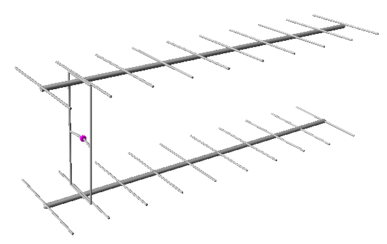
- YBN 3+7 SAT
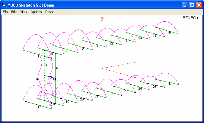
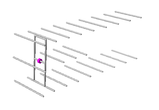
Simulating the YU0B 11+11 Beam with Skeleton Slot Driven Element
the Origin
I believe this antenna is a result of the efforts of the Belgrad radio amateurs to create an improved antenna
for working 2 m EME. With the K8AT skeleton slot driven double boom Yagi as a starting point. As the K8AT antenna
showed a novelty, which is a very close coupling of the two D1 elements to the lower and upper horziontal rods
of the slots loop. The EIMAC paper AS-49-18 features the K8AT EME Array and reads "Please note the difference in the design
from the standard J slot antenna. The very closely coupled first director is the innovation of John Yurek, K3PGP."
the Artifice
For the YU0B antenna the coupling distance between the slots horizontal rods and D1s is just 18 mm.
With that close a coupling the slot and its flanking pair of D1's appear as a single exciter.
The following image shows the skeleton slot and upper & lower D1:

the Publications
This design was initially published in the 'YU VHF UHF Bulletin's Special edition Antennas in 1980.
The YU0B double boom beam has been described in the article 'YU0B ANTENA' in RADIO-AMATER 10/82 by Dragoslav Dobričić, YU1AW
And also in a paper 'ANALIZA ANTENE YU0B' by Némethy Ištván, YU7EW dated March 2003.
Whose later callsings were YU1NWN, YU7NWN, 4N2I, and after 17th October 2007: YT3I
There are many derivates of the 11+11 element YU0B antenna, with 8+8 and 9+9 elements.
The following is only valid and of use for the particular '11+11' original YU0B antenna.
The '11+11' means 10 parasitc elements per boom plus 1 each as horizontal part for the slot.
So we already know how good is the YU0B Beam is in case we have those articles / papers at hand
In the paper 'ANALIZA ANTENE YU0B' YU7EW (the later YT3I) determined a forward gain of 11.65 ... 11.97 dBd with an F/B of 22.68 ... 23.99 dB depending on the applied segment density. For this he used AO 6.30 by K6STI. We note that he also had a challenge in building a model with a sound segmentation density for the challenges it holds. Read more about Average Gain (AG or AGV) and this antennas challenges when modelled for a NEC based simulation tool further down the page.
Find detailled numbers for gain, F/B, F/R and also Antenna G/T below. But the main question whether the DL7KM beam or the YU0B beam has the upper hand ... well ... both have been made around the early 80ths, have almost same boom length ... but looking at the Antenna G/T we find a -11.25 dB for the DL7KM vs. a -9.57 dB for the YU0B (both as single antennas). So the YU0B is far ahead. But mind the DL7KM is covering the whole 2 m band while the YU0B is an SSB band design only.
Nevertheless I did my own simulation to share with you on this website. So lets analyse the YU0B beam ...
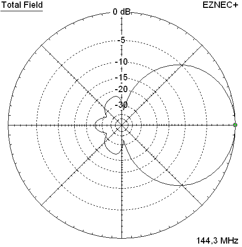
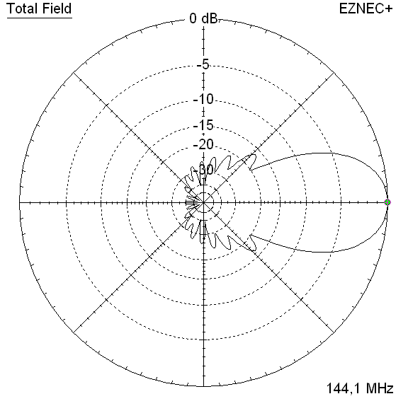
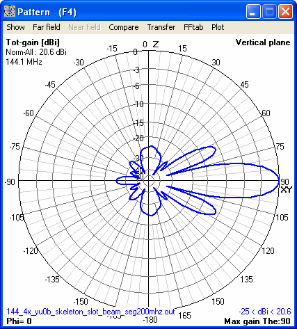
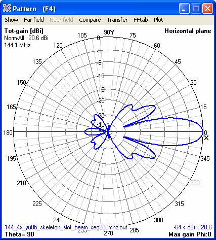
Original design
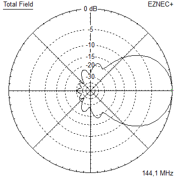
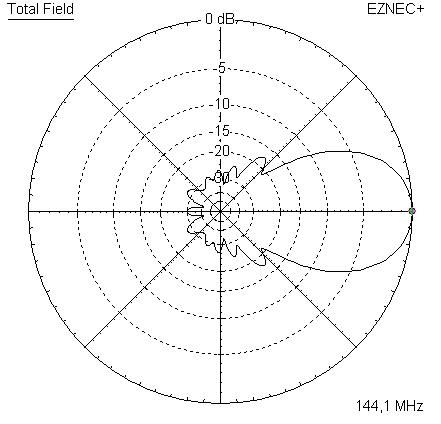
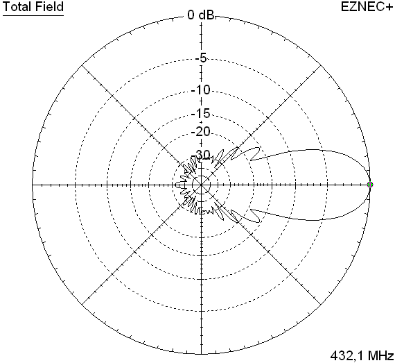
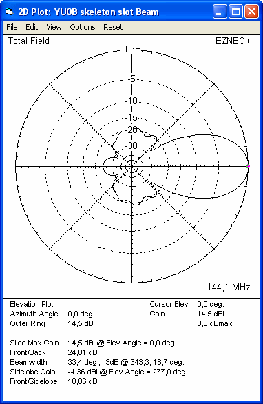
Elevation and azimuth pattern plots
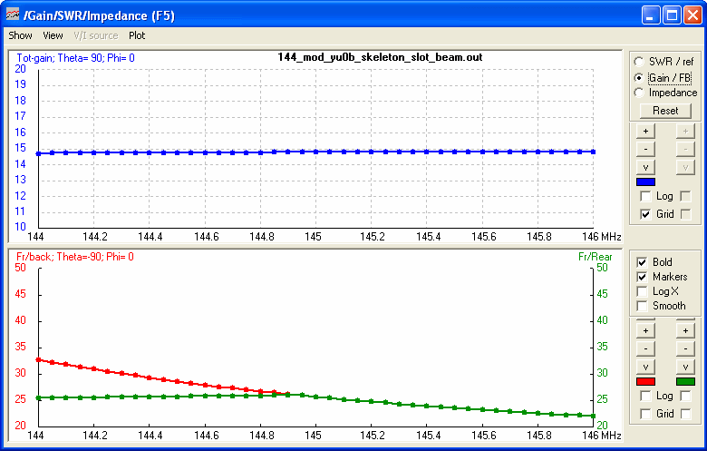
Absolute forward gain is difficult to judge with this antennas model due to the very close coupling of the pair of D1's with the skeleton slot. It is around 14.4 .. 14.5 dBi.

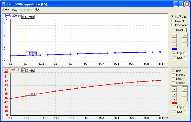
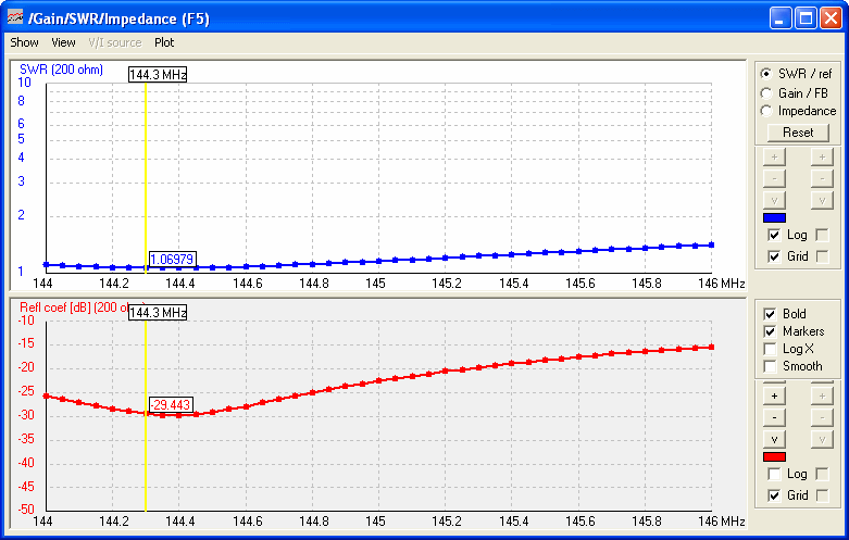
VSWR and Return Loss
The YU0B is planned to show a Z = 200 ohms at the feed point. In his article YU7EW simulated
the Yagi with AO PRO 6.30 by K6STI and found a Z ~ 220 + 42 ohms (VSWR = 1.24) @ 144.2 MHz
My simulation of the YU0B Beams Return Loss and SWR simulated with 4nec2 (using an EZNEC+ v 5 made file auto
segmented at 380 MHz) shows a Z ~ 220 + 50 ohms @ 144.2 MHz for a good willing simulation
YU0B beam model response to variation of the segmentation density
Modelling the YU0B for correct results may be named a though business. If not complexity of the skeleton slot alone with its multitude of rectangular angles is a challenge, the very close coupling to the adjacent pair of D1's for sure adds some spice to that. As no nec kernel handles wires closer than 0.01 wave length without some divergence.
As a result of the sum of challenges the AGV over segmentation density chart line shows a reverse to the ordinary characteristic. Instead of starting with a low AGV around 0.75 for a few segments per wire and then swinging up towards an AG of 0.99 we find the starting point with a minimum segments number right overshooting the theoretical 100 percent or 1.000 as AGV to 120 percent or 1.2 as factorised number. Which seems to behave in the expected way when being auto segmented with EZNEC at an input frequency of 200 MHz ( = 14 .. 12 segments per parasitc element).
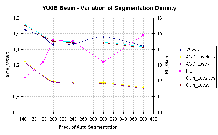
Read about model wire segmentation here
Read about Average Gain here
Read more about Average Gain and AG correction here
Stacking Distances & Performance
Much has been stated about optimum stacking distances of the two planes of the parasitic elements in YU1AW's article and there is further read on my website about the DL7KM double boom beam. I stick to the DL6WU formula. In his paper 'ANALIZA ANTENE YU0B' by Némethy Ištván, YU7EW did extensive simulations for the stacked YU0B.
Stacking Dist. DL6WU Formula
top-to-bottom (H-Plane)     3.62 m or 11.9 ft*
side-by-side (E-Plane)      3.28 m or 10.8 ft*

(*) = for center of antennas ie. in the middle point between the booms
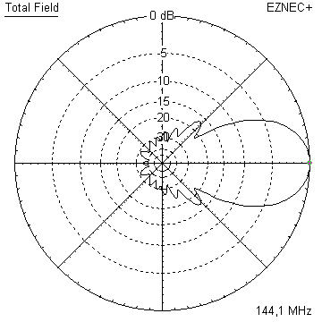
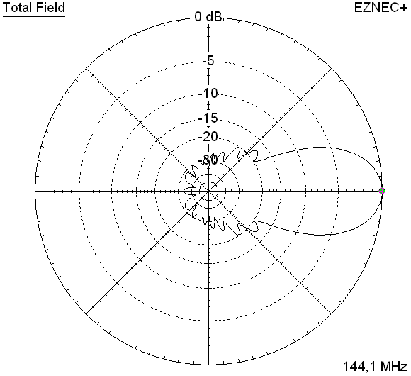
Elevation and azimuth plots for a 4 bay of YU0B beams at stacking distances acc. DL6WU's formula
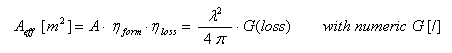
Design modification
Gearing up ... with first simulated patterns at hand I thought about applying same style of modifications to the YU0B beam that I did to the DL7KM beam. Thus I applied a small inner structure. In which an extraordinary reflector length of 1060 mm showed best results, deleted one director und placed the remaining ones in a new way.
To enable easy adaptions I restriced the redesign to shorter elements if modified and left the slot itself untouched.
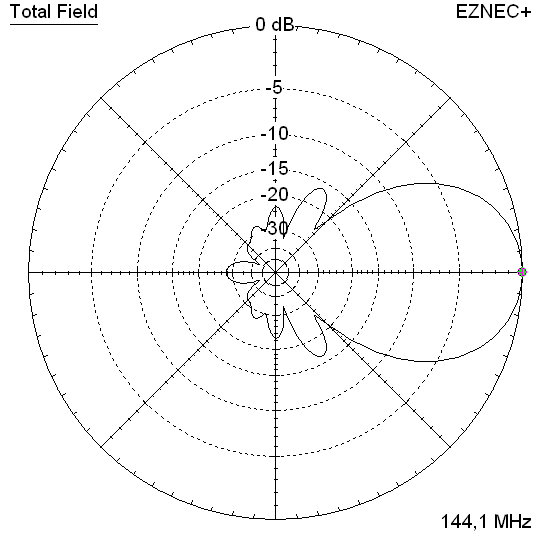
Modified design with small inner structure
Original YU0B Beam (black line) vs. anticipated modified design ( blue line)

I elemininated one element from the wave guiding structure each, spread the remaining ones more sensibly over the boom length, modified their lengths, moved the reflectors closer in, and added three inner directing elements - which play a major role in tying up the beams pattern.
Performance Data of original and modified Design
                     Orig. YU0B    Mod. YBN
Gain vs. isotr. Rad.  14.5 dBi*     14.7 dBi**
Gain vs. Dipole       12.3 dBD*     12.6 dBD
F/B                  -24.0 dB      -31.5 dB
F/R                  -19.8 dB      -25.5 dB
Impedance               200 ohms      200 ohms
VSWR Band Width       1.53:1***     1.16:1***
Mechan. Length        3628 mm       3628 mm
Electr. Length        1.74 λ        1.74 λ

Corrected Average Gain Data for the single beam
T_loss                 3.2 K          3.3 K
Antenna Temp.        256.2 K        228.3 K
G/T (single ant.)    -9.57 dB       -8.86 dB
*) 14.5 dBi at an Average Gain of 0.xxx for the lossy model and 14.xx dBi at an AG of 0.xxx for the lossless model. With AG correction per KF2YN applied the resulting gain is 14.xx dBi or xx.xx dBD.
**) 14.63 dBi at an Average Gain of 0.965 for the lossy model and 14.67 dBi at an AG of 0.976 for the lossless model. With AG correction per KF2YN applied the resulting gain is 14.73 dBi or 12.58 dBD.
***) as in VE7BQH G/T table = at 145.00 MHz
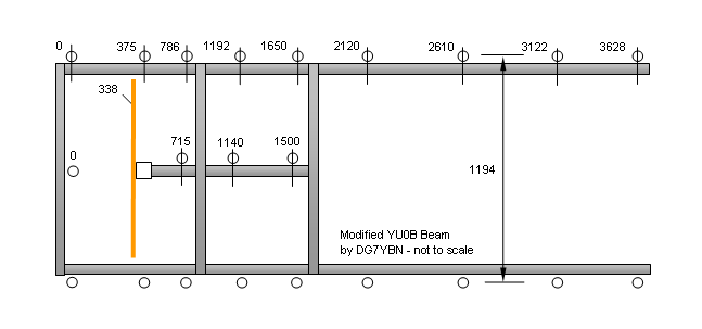
The Half Power Beam Width of the original design might suggest more gain then there is in it. Which is due to the unusual pattern characteristic compared to ordinary Yagi designs. Thus we meet a quite different form factor η_loss for the standard equation for effective area and gain:
With G(loss) = numeric gain including losses on wires. As the equivalent to multiplying the capture area A with η_loss on the other side of the equation. We produce G(loss) "automatically" when measuring a real Yagi or simulating with right choice of wire material; where we name it "G" or "Gain" only. Which is not the urging issue here, but explains the formula to extend. With a Yagi structure, same efficiency provided, and one time stacked to x.x m and on the other hand stacked to x.x m we yield quite a difference in the effective area Aeff. An thus in the gain number too.
Geometry of the modified design
No BC, no SBC given yet. Boomless numbers as used in the NEC file only.
For the given below measures elements are of Ø 5 mm, the skeleton slot is made of Ø 5 mm rod(s). Due to the rectangular, loop style driver I suggest no SBC here. The common BC must meet the way your elements shall be fastened. Find BC numbers on my BC-page
5 mm elements - upper and lower boom
       Refl.    DE       D1       D2       D3       D4       D5       D6      D7      D8
Pos.   0        338      375      786      1192     1650     2120     2610    3122    3628 mm
Lgth.  1030     380      942      914      908      892      885      876     858     848  mm

5 mm elements - short center boom
       Refl.    DE       D1       D2       D3
Pos.   0        338      715      1140     1500 mm
Lgth.  1120      -       800      764      794  mm
The skeleton slots wire diameter is 5 mm. Circumfence of the loops and all measures are identical to the original YU0B Beam. Which are 1140 x 380 mm. Note: The lower booms elements, originally being on the boom, they are mounted facing the downside in this redesign!
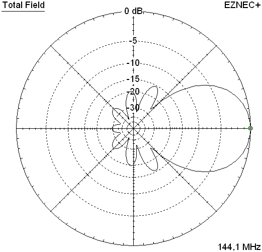
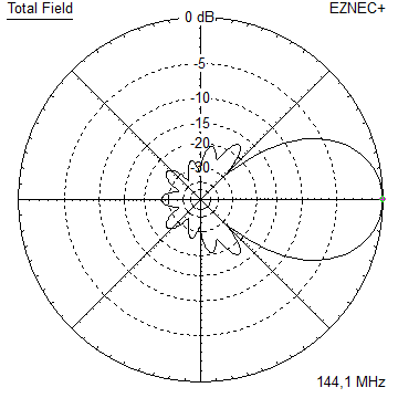
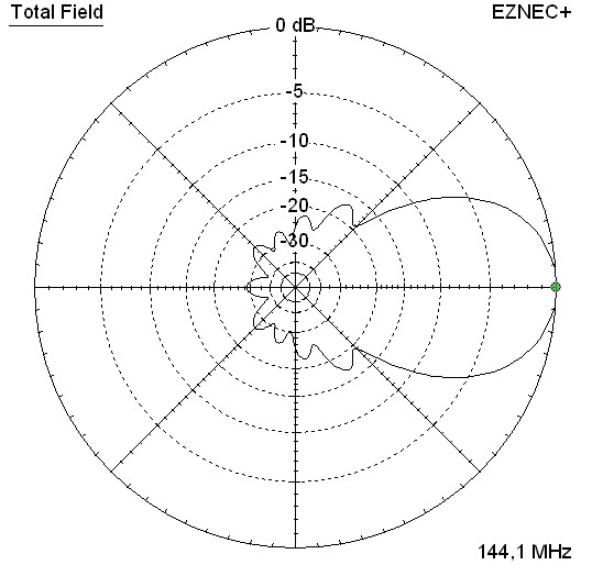
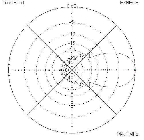
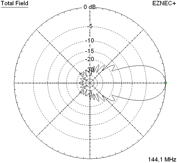
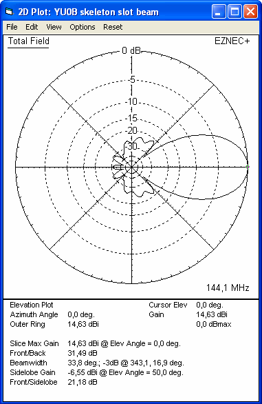
Pattern and VSWR Plots of the modified design
Elevation and Azimuth plot at 144.1 MHz

RL and SWR plot - simulated
Gain, F/B and F/R plot - simulated
Downloads
EZNEC file of the YU0B Beam
EZNEC file of the modified YU0B Beam
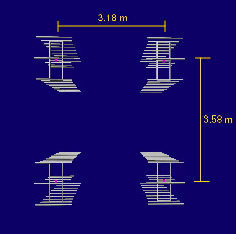
Stacking the modified YU0B Beam
Stacking Dist. DL6WU Formula
top-to-bottom (H-Plane) 3.58 m or 11.7 ft ✶
side-by-side (E-Plane) 3.18 m or 10.4 ft ✶
(✶) = for center of antennas ie. in the middle point between the booms
2 modified YU0B Beams side-by-side, gain = 17.57 dBi or 15.42 dBD
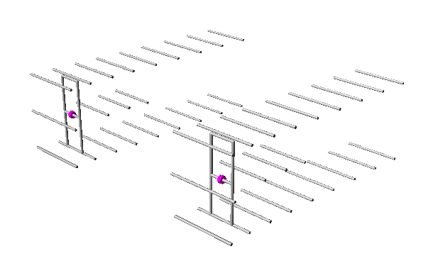
3D pattern of 2 x modified YU0B Beam side-by-side (4NEC2)
Modfied DL7KM Beam as a 4 Bay
Stacking Scheme
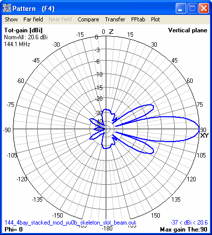
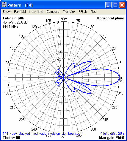
The simulation with lossy antenna elements shows:
Antenna G/T = -3.03 dB at an AG of 0.982
Gain = 20.63 dBi, T_pattern = 231.4 K, T_loss = 5.3 K, Antenna Temperature = 232.5 K
The simulation with lossless antenna elements shows:
Antenna G/T = -2.98 dB at an AG of 0.992
Gain = 20.67 dBi, T_pattern = 231.4 K, T_loss = 2.2 K, Antenna Temperature = 231.8 K
Applying the AG Correction per KF2YN
leads to the true numbers of
Antenna G/T = -2.99 dB Gain = 20.66 dBi or 18.51 dBd, T_loss = 2.9 K, Antenna Temperature = 232.0K
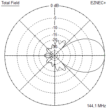
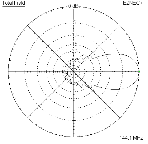
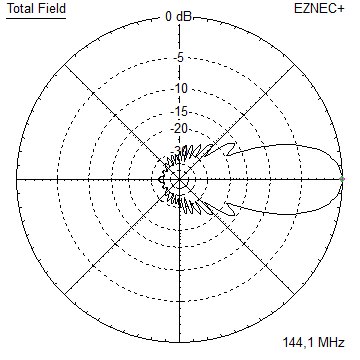
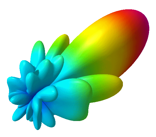
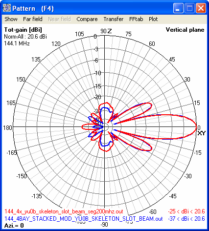
And finally, a comparison of the of the original and modified YU0B beams elevation patterns as 4 bays
73, Hartmut, DG7YBN