-
• Main Page
- • Home
• Antennas - • 432 MHz
- YBN 70-5mA 0.5 m 432 MHz blue print of the YBN 2-5m 50 ohms high F/B direct feed 144 MHz Low Noise Yagi
3D Plot
- YBN 70-8zA 1.5 m high gain 28 ohms Yagi.
A design partly based on the hardware of the WY-7010, turning it into a 8 ele. 28 ohms Yagi with cleaner pattern, +1.8 dB gain and better VSWR.
Azimuth Plot
- YBN 70-14wzTune up your 19 ele. Tonna!
A design based on the hardware of the F9FT, turning it into a 14 ele. OWL with cleaner pattern, +0.3 dB gain and SWR less than 1.2 from 430 to 440 MHz
Azimuth Plot
- YBN 70-14+4wA 3.2 m very wideband 50 ohms Yagi with reflector wall that covers the whole 70 cm band with ease
Elevation Plot
- GTV 70-2wA 0.14 m GTV useful for portable operation and up to the satellit band and handheld activities of any kind
Elevation Plot
- GTV 70-3wA 0.21 m GTV useful for portable operation and up to the satellit band and lower noise stacks of any kind
Elevation Plot
- GTV 70-4mA 0.34 m GTV useful for portable operation up to the satellit band and lower noise stacks of any kind
Elevation Plot
- GTV 70-7wA 0.96 m GTV useful for portable operation up to the satellit band and lower noise stacks of any kind
Elevation Plot
- GTV 70-7nA 1.1 m 432 MHz blue print of the low impedance, yet 50 ohms direct feed 144 MHz Low Noise Yagi introduced in Dubus 1/2013
Elevation Plot
- GTV 70-8nA 1.3 m 432 MHz GTV with high gain but low backlobe volume. Makes a very compact 4 Yagi bay for QRP EME or contesting.
Elevation Plot

- GTV 70-9wA 1.44 m GTV ment to be useful as a vertical stack for contesting or be an ideal small size portable Yagi
Elevation Plot
- GTV 70-10wA 1.63 m GTV useful for portable operation up to the satellit band and lower noise stacks of any kind
Elevation Plot
- GTV 70-11wA 2.01 m GTV ment to be useful as a vertical stack for contesting or be an ideal small size portable Yagi or minimum size EME 4 bay
Elevation Plot
- GTV 70-13mA 2.5 m GTV ment to be useful as a vertical stack for contesting or be an ideal small size portable Yagi or minimum size EME 4 bay
Elevation Plot
- GTV 70-14m2.9 m version of the low impedance, yet 50 ohms direct feed Low Noise Yagi with bent DE introduced in Dubus 1/2013
Elevation Plot
- GTV 70-17m3.7 m version of the low impedance, yet 50 ohms direct feed Low Noise Yagi with bent DE introduced in Dubus 1/2013
Elevation Plot
- GTV 70-18w4.0 m version of the low impedance, yet 50 ohms direct feed Low Noise Yagi with bent DE introduced in Dubus 1/2013
Elevation Plot
- GTV 70-19m4.2 m version of the low impedance, yet 50 ohms direct feed Low Noise Yagi with bent DE introduced in Dubus 1/2013
Elevation Plot
- GTV 70-21n4.7 m version of the low impedance, yet 50 ohms direct feed Low Noise Yagi with bent DE introduced in Dubus 1/2013
Elevation Plot
- GTV 70-23m5.3 m version of the low impedance, yet 50 ohms direct feed Low Noise Yagi with bent DE introduced in Dubus 1/2013
Elevation Plot
- GTV 70-25m5.9 m version of the low impedance, yet 50 ohms direct feed Low Noise Yagi with bent DE introduced in Dubus 1/2013
Elevation Plot
- GTV 70-30m7.3 m version of the low impedance, yet 50 ohms direct feed Low Noise Yagi with bent DE introduced in Dubus 1/2013
Elevation Plot
- GTV 70-34w8.5 m version of the low impedance, yet 50 ohms direct feed Low Noise Yagi with bent DE introduced in Dubus 1/2013
Elevation Plot
- GTV 70-46w12.0 m version of the low impedance, yet 50 ohms direct feed Low Noise Yagi with bent DE introduced in Dubus 1/2013
Elevation Plot
- DL6WU YagisThe DL6WU Longyagi Series
Sample plot: 32 el. plus 4 x reflector
Elevation Plot

- YBN 70-5m
YBN 70-14 plus 4 w Yagi with straight Driven Element
Wideband version ... 430 to 440 MHz
As a very wideband Yagi it has a 4 x reflector wall fitted to acheive very low back lobes across
430-440 MHz. Simulated Return Loss (S11) is better -30 dB from 430 to 440 MHz. Due to length and whole
70 cm band coverage it may serve for anything from repeater to SSB band up to satellite operations.
Design date: Oct. 2020.
The Yagi is a 50 ohms direct feed design which of coarse also can be built with a common folded dipole.
The reflector wall follows DL6WU's way of increasing F/B on a wideband Longyagi. With this design I do
not intend to break any records regarding Antenna G/T or gain. This Yagi is intended an easy to reproduce,
always and anywhere on the band clean pattern design with a solid 16 dBi of gain.
Current distribution

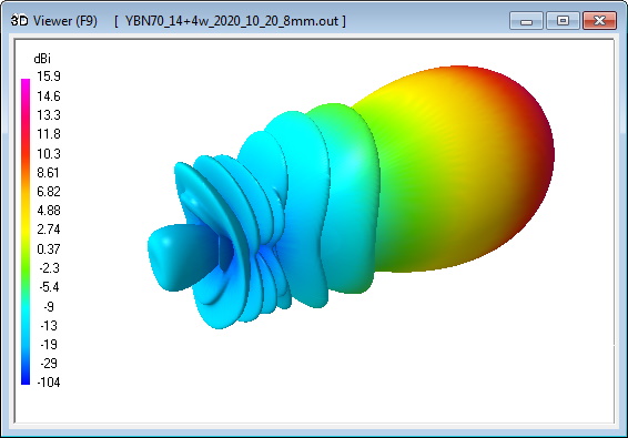
3D Pattern (432.1 MHz)
Return Loss and VSWR (424 - 444 MHz)
Performance Data
Specs: with 8.00 mm elements @ 432.1 MHz
Gain vs. isotr. Rad.  16.0 dBi
Gain vs. Dipole       13.9 dBD
-3 dB E-plane         31.8 deg.
-3 dB H-plane         34.0 deg.
F/B                  -31.0 dB
F/R                  -27.4 dB
Impedance               50 ohms
Mechan. Length        3244 mm incl. 2 x 40 mm stand off
Electr. Length        4.56 λ

Stacking dist. h-pol.
top-to-bottom         1.26 m or 4.13 ft
side-by-side          1.34 m or 4.40 ft
How many OMs have been looking up this design?
Geometry
Table 1: 70 cm section, 8.00 mm elements on a 20 x 20 mm boom:
"Ready to saw and drill" data for mounting elements on boom with BC according DG7YBN for standard insulators as sold by WiMo, Tino's Funkshop, HF Kits.nl, 7arrays:
|
Boom shape: square Boom: 20 x 20 mm Offset rear: 40 mm Offset front: 40 mm |
|

Note: This includes an SBC of 1.28 mm
Note: This table starts with the DIPOLE!
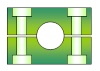
Reflector Wall, also 40 mm offset at both ends.
The reflector wall is to be mounted at 40 mm minus height of insulators from rear end.
Table 2: 70 cm section, 5.00 mm elements on a 20 x 20 mm boom using hydraulic clamps (like Stauff) or SM7DTT insualtors:
"Ready to saw and drill" data for mounting elements on boom with BC according DG7YBN for using hydraulic clamps (like Stauff) or SM7DTT insulators:
|
Boom shape: square Boom: 20 x 20 mm Offset rear: 40 mm Offset front: 40 mm |
|
Note: This includes an SBC of 1.28 mm
Note: This table starts with the DIPOLE!
Reflector Wall, also 40 mm offset at both ends.
The reflector wall is to be mounted at 40 mm minus height of insulators from rear end.
Radiation Pattern and VSWR Plots
Elevation and Azimuth plot at 432.1 MHz (8.0 mm ele.)


Elevation and Azimuth plot at 434.0 MHz

Elevation and Azimuth plot at 436.0 MHz
Elevation and Azimuth plot at 438.0 MHz


SWR and Return Loss plots - simulated with 4nec2
Downloads
none so far
Stacking
Stacking Dist.    DL6WU Formula
H-plane               1.26 m
E-plane               1.34 m
2 x vertical YBN 70-14 plus 4 w

4 x vertical YBN 70-14 plus 4 w
Data for elements 8.00 mm @ 432.1 MHz
Gain vs. isotr. Rad.  21.8 dBi
Gain vs. Dipole       19.7 dBD
F/B                  -29.8 dB
F/R                  -29.8 dB
T_ant                 51.4 K*
G/T                    4.77 dB*
Theoretical numbers, no phasing line losses
nor imperfections caused by mast included
*) T_sky = 27 K, T_earth = 1800 K as in newer VE7BQH G/T table
3D pattern plot with 4nec2's 3D viewer
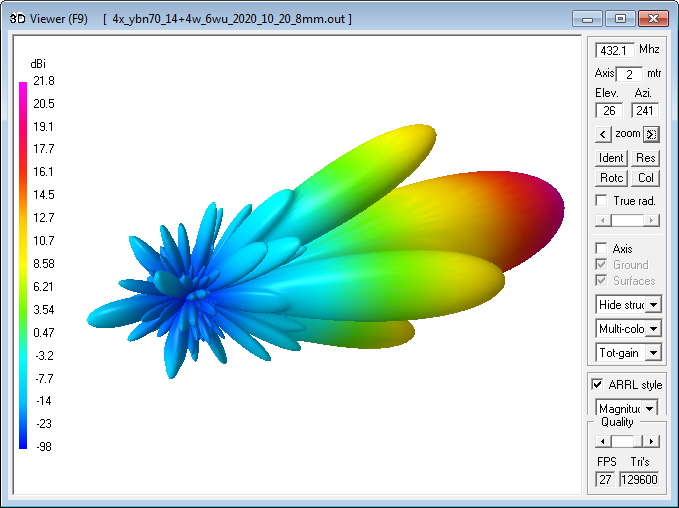
Finally a G/Ta analysis with AGTC as MS Excel tool:
A 4 Yagi bay at DL6WU stacking distances v + h shows a corrected G/Ta of 4.77 dB at T:earth = 1800 K, T_sky = 27 K.
73, Hartmut, DG7YBN