-
• Main Page
- • Home
• Antennas - • 432 MHz
- YBN 70-5mA 0.5 m 432 MHz blue print of the YBN 2-5m 50 ohms high F/B direct feed 144 MHz Low Noise Yagi
3D Plot
- YBN 70-8zA 1.5 m high gain 28 ohms Yagi.
A design partly based on the hardware of the WY-7010, turning it into a 8 ele. 28 ohms Yagi with cleaner pattern, +1.8 dB gain and better VSWR.
Azimuth Plot
- YBN 70-14wzTune up your 19 ele. Tonna!
A design based on the hardware of the F9FT, turning it into a 14 ele. OWL with cleaner pattern, +0.3 dB gain and SWR less than 1.2 from 430 to 440 MHz
Azimuth Plot
- YBN 70-14+4wA 3.2 m very wideband 50 ohms Yagi with reflector wall that covers the whole 70 cm band with ease
Elevation Plot
- GTV 70-2wA 0.14 m GTV useful for portable operation and up to the satellit band and handheld activities of any kind
Elevation Plot
- GTV 70-3wA 0.21 m GTV useful for portable operation and up to the satellit band and lower noise stacks of any kind
Elevation Plot
- GTV 70-4mA 0.34 m GTV useful for portable operation up to the satellit band and lower noise stacks of any kind
Elevation Plot
- GTV 70-7wA 0.96 m GTV useful for portable operation up to the satellit band and lower noise stacks of any kind
Elevation Plot
- GTV 70-7nA 1.1 m 432 MHz blue print of the low impedance, yet 50 ohms direct feed 144 MHz Low Noise Yagi introduced in Dubus 1/2013
Elevation Plot

- GTV 70-8nA 1.3 m 432 MHz GTV with high gain but low backlobe volume. Makes a very compact 4 Yagi bay for QRP EME or contesting.
Elevation Plot

- GTV 70-9wA 1.44 m GTV ment to be useful as a vertical stack for contesting or be an ideal small size portable Yagi
Elevation Plot
- GTV 70-10wA 1.63 m GTV useful for portable operation up to the satellit band and lower noise stacks of any kind
Elevation Plot
- GTV 70-11wA 2.01 m GTV ment to be useful as a vertical stack for contesting or be an ideal small size portable Yagi or minimum size EME 4 bay
Elevation Plot
- GTV 70-13mA 2.5 m GTV ment to be useful as a vertical stack for contesting or be an ideal small size portable Yagi or minimum size EME 4 bay
Elevation Plot
- GTV 70-14m2.9 m version of the low impedance, yet 50 ohms direct feed Low Noise Yagi with bent DE introduced in Dubus 1/2013
Elevation Plot
- GTV 70-17m3.7 m version of the low impedance, yet 50 ohms direct feed Low Noise Yagi with bent DE introduced in Dubus 1/2013
Elevation Plot
- GTV 70-18w4.0 m version of the low impedance, yet 50 ohms direct feed Low Noise Yagi with bent DE introduced in Dubus 1/2013
Elevation Plot
- GTV 70-19m4.2 m version of the low impedance, yet 50 ohms direct feed Low Noise Yagi with bent DE introduced in Dubus 1/2013
Elevation Plot
- GTV 70-21n4.7 m version of the low impedance, yet 50 ohms direct feed Low Noise Yagi with bent DE introduced in Dubus 1/2013
Elevation Plot
- GTV 70-23m5.3 m version of the low impedance, yet 50 ohms direct feed Low Noise Yagi with bent DE introduced in Dubus 1/2013
Elevation Plot
- GTV 70-25m5.9 m version of the low impedance, yet 50 ohms direct feed Low Noise Yagi with bent DE introduced in Dubus 1/2013
Elevation Plot
- GTV 70-30m7.3 m version of the low impedance, yet 50 ohms direct feed Low Noise Yagi with bent DE introduced in Dubus 1/2013
Elevation Plot
- GTV 70-34w8.5 m version of the low impedance, yet 50 ohms direct feed Low Noise Yagi with bent DE introduced in Dubus 1/2013
Elevation Plot
- GTV 70-46w12.0 m version of the low impedance, yet 50 ohms direct feed Low Noise Yagi with bent DE introduced in Dubus 1/2013
Elevation Plot
- DL6WU YagisThe DL6WU Longyagi Series
Sample plot: 32 el. plus 4 x reflector
Elevation Plot

- YBN 70-5m
GTV 70-18w Yagi with bent Driven Element
Wideband version covering the full 70 cm band with nice G/T at EME & SSB part of band
This Yagi has very low back lobes for its length. It may serve as single antenna for portable
use and certainly make a useful 4 x vertical stack. It makes a quiet contest antenna due to its
high F/B. The bent DE (K6STI style) transforms from approx. 17 ohms to 50 ohms at feed point.
This Yagi is based on the GTV 2-18w design. Date of issuing this design: 22nd of Aug. 2021
Current distribution


Performance Data
Specs: with 8 mm elements @ 432.1 MHz
Gain vs. isotr. Rad.  17.6 dBi
Gain vs. Dipole       15.4 dBD
-3 dB E-plane         25.8 deg.
-3 dB H-plane         26.8 deg.
F/B                  -33.5 dB
F/R                  -30.1 dB
Impedance               50 ohms
Mechan. Length        3969 mm incl. 2 x 40 mm stand off
Electr. Length        5.61 λ

VSWR Bandwidth        1:1.08 (as in VE7BQH Antenna Table)

Stacking dist. h-pol.
top-to-bottom         1.51 m or 4.95 ft
side-by-side          1.57 m or 5.14 ft
How many OMs have been looking up this design?
Geometry
Ø8 mm Elements - On Boom - Dimensions (BC acc. DG7YBN)

|
Ele. 8.0 mm DE 10 mm Boom 20 x 20 mm |
"Ready to saw and drill" data for mounting elements on boom with BC according DG7YBN for standard insulators as sold by WiMo, Tino's Funkshop, 7arrays, HF-Kits.nl:
Includes an SBC of 1.14 mm

Ø8 mm Elements - On Boom - Dimensions (BC acc. DG7YBN)

|
Ele. 8.0 mm DE 10 mm Boom 25 x 25 mm |
"Ready to saw and drill" data for mounting elements on boom with BC according DG7YBN for standard insulators as sold by WiMo, Tino's Funkshop, 7arrays, HF-Kits.nl:
Includes an SBC of 1.14 mm

Table 2: GTV 70-21n, 4 mm elements through boom:
"Ready to saw and drill" data for mounting elements through boom with BC according SM5BSZ's BC.exe:
Note: with through Boom BC it is important to stick to the boom end offsets given below!
Metric Boom 20 x 20 x 2 mm
|
Boom shape: square Boom dim: 20 x 20 mm Wall thickn.: 2.0 mm Holes in boom: 6.0 mm Offset rear: 40 mm Offset front: 40 mm |
|

Note: with through Boom BC it is important to stick to the boom end offsets given below!
Metric Boom 25 x 25 x 2 mm
|
Boom shape: square Boom dim: 25 x 25 mm Wall thickn.: 2.0 mm Holes in boom: 6.0 mm Offset rear: 40 mm Offset front: 40 mm |
|
Note: with through Boom BC it is important to stick to the boom end offsets given below!

Imperial Boom 1" - El. 4.00 mm
|
Boom shape: square Boom dim: 1 x 1 inch Wall thickn.: 1.6 mm Holes in boom: 6.0 mm Offset rear: 40 mm Offset front: 40 mm |
|
Note: All the above include a "Segmentation Density Correction" (SBC) of 1.14 mm plus an offset of 0.70 mm per element = 1.84 mm
for compensation of the insulators (7arrays.com
Note: with through Boom BC it is important to stick to the boom end offsets given below!
Read abt. the SBC here
Imperial Boom 1" - El. 4.763 mm or 3/16 inch
|
Boom shape: square Boom dim: 1 x 1 inch Wall thickn.: 1.4 mm Holes in boom: 7.7 mm Offset rear: 40 mm Offset front: 40 mm |
|

Note: All the above include a "Segmentation Density Correction" (SBC) of 1.14 mm plus an offset of 0.70 mm per element = 1.84 mm
for compensation of the insulators in combination with SM5BSZ'S BC.exe values.
Note: with through Boom BC it is important to stick to the boom end offsets given below!
Read abt. the SBC here
For making of a 'Blade Dipole'
Sketch of Bent Dipole
Radiation Pattern and VSWR Plots
Elevation and Azimuth plot at 432.1 MHz (8 mm ele.)

Elevation and Azimuth plot at 435 MHz (8 mm ele.)

Elevation and Azimuth plot at 439 MHz (8 mm ele.)

VSWR and Return Loss plots - simulated with 4nec2

This Yagi as XPOL 435 MHz Version

EZ/AZ Plot (4 mm ele.):
h/v-plane offset = 680 mm,
Stacking per DL6WU h/v mean dist. = 1.54 m
This Yagi with 4 mm elements through a 25 x 25 mm boom Metric Boom 25 x 25 x 2 mm
|
Boom shape: square Boom dim: 25 x 25 mm Wall thickn.: 2.0 mm Holes in boom: 6.0 mm Offset rear: 40 mm h-plane,720 mm v-plane Offset front: 720 mm h-plane, 40 mm v-plane |
|
Note: with through Boom BC it is important to stick to the boom end offsets given below!
Includes an SBC of 1.84 mm

Stacking
As on 432 MHz the Y-factor = T_earth / T_sky is so high, I see little chances to
improve an array's RX performance by using "Over Stacking" distances. However, depending on
the level of local QRM it might be worthwhile to try a decreased distance, especially in the H-plane.
Stacking Dist.    DL6WU Formula
H-plane               1.51 m or 4.95 ft
E-plane               1.57 m or 5.14 ft
A 4 Yagi bay
Elev. Plot

Azim. Plot
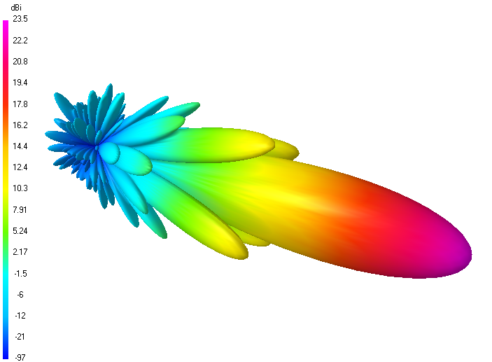
4 bay data (8 mm ele.):
Gain vs. isotr. Rad.  23.5 dBi
Gain vs. Dipole       21.3 dBD
-3 dB H-plane, appr.   5.8 deg.
-3 dB E-plane, appr.   5.8 deg.
F/B                  -34.0 dB
F/R                  -30.1 dB
T_ant, total          61.8 K*
G/T                   5.56 dB*

at Tsky = 27 K, Tearth = 1800 K as in newer VE7BQH Antenna Table
3D pattern plot with 4nec2's 3D viewer
Antenna G/T with AGTC lite VBA-version:

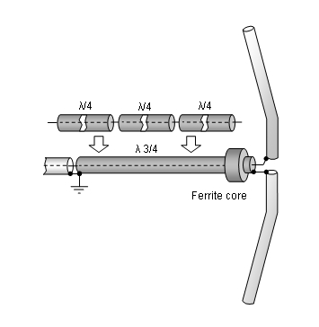
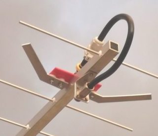
Symmetrising 50 to 50 ohms feedline to 432 MHz Bent DE
The principle is similar to the 1/4 Lambda coax. Adding 2 x 1/4 Lambda or a half wave line does not change anything but allows
to form a gentle bow below the boom or until behind the Reflector. Follow practical construction hints on "Building a Yagi" page.
 Attenzione!
Take care when lengthening the coax, measure the actual electrical length instead of considering v-factors specified in a catalogue only.
Attenzione!
Take care when lengthening the coax, measure the actual electrical length instead of considering v-factors specified in a catalogue only.A good choice may be the diam. 5 mm PTFE coax RG-142 B/U: real resonate length (432.2 MHz as 3/4 Lambda) shield-shield is around 348 mm
 Find more information on Phasing & Matching Lines page
 73, Hartmut, DG7YBN