-
• Main Page
- • Home
• Antennas - • 432 MHz
- YBN 70-5mA 0.5 m 432 MHz blue print of the YBN 2-5m 50 ohms high F/B direct feed 144 MHz Low Noise Yagi
3D Plot
- YBN 70-8zA 1.5 m high gain 28 ohms Yagi.
A design partly based on the hardware of the WY-7010, turning it into a 8 ele. 28 ohms Yagi with cleaner pattern, +1.8 dB gain and better VSWR.
Azimuth Plot
- YBN 70-14wzTune up your 19 ele. Tonna!
A design based on the hardware of the F9FT, turning it into a 14 ele. OWL with cleaner pattern, +0.3 dB gain and SWR less than 1.2 from 430 to 440 MHz
Azimuth Plot
- YBN 70-14+4wA 3.2 m very wideband 50 ohms Yagi with reflector wall that covers the whole 70 cm band with ease
Elevation Plot
- GTV 70-2wA 0.14 m GTV useful for portable operation and up to the satellit band and handheld activities of any kind
Elevation Plot
- GTV 70-3wA 0.21 m GTV useful for portable operation and up to the satellit band and lower noise stacks of any kind
Elevation Plot
- GTV 70-4mA 0.34 m GTV useful for portable operation up to the satellit band and lower noise stacks of any kind
Elevation Plot
- GTV 70-7wA 0.96 m GTV useful for portable operation up to the satellit band and lower noise stacks of any kind
Elevation Plot
- GTV 70-7nA 1.1 m 432 MHz blue print of the low impedance, yet 50 ohms direct feed 144 MHz Low Noise Yagi introduced in Dubus 1/2013
Elevation Plot

- GTV 70-8nA 1.3 m 432 MHz GTV with high gain but low backlobe volume. Makes a very compact 4 Yagi bay for QRP EME or contesting.
Elevation Plot

- GTV 70-9wA 1.44 m GTV ment to be useful as a vertical stack for contesting or be an ideal small size portable Yagi
Elevation Plot
- GTV 70-10wA 1.63 m GTV useful for portable operation up to the satellit band and lower noise stacks of any kind
Elevation Plot
- GTV 70-11wA 2.01 m GTV ment to be useful as a vertical stack for contesting or be an ideal small size portable Yagi or minimum size EME 4 bay
Elevation Plot
- GTV 70-13mA 2.5 m GTV ment to be useful as a vertical stack for contesting or be an ideal small size portable Yagi or minimum size EME 4 bay
Elevation Plot
- GTV 70-14m2.9 m version of the low impedance, yet 50 ohms direct feed Low Noise Yagi with bent DE introduced in Dubus 1/2013
Elevation Plot
- GTV 70-17m3.7 m version of the low impedance, yet 50 ohms direct feed Low Noise Yagi with bent DE introduced in Dubus 1/2013
Elevation Plot
- GTV 70-18w4.0 m version of the low impedance, yet 50 ohms direct feed Low Noise Yagi with bent DE introduced in Dubus 1/2013
Elevation Plot
- GTV 70-19m4.2 m version of the low impedance, yet 50 ohms direct feed Low Noise Yagi with bent DE introduced in Dubus 1/2013
Elevation Plot
- GTV 70-21n4.7 m version of the low impedance, yet 50 ohms direct feed Low Noise Yagi with bent DE introduced in Dubus 1/2013
Elevation Plot
- GTV 70-23m5.3 m version of the low impedance, yet 50 ohms direct feed Low Noise Yagi with bent DE introduced in Dubus 1/2013
Elevation Plot
- GTV 70-25m5.9 m version of the low impedance, yet 50 ohms direct feed Low Noise Yagi with bent DE introduced in Dubus 1/2013
Elevation Plot
- GTV 70-30m7.3 m version of the low impedance, yet 50 ohms direct feed Low Noise Yagi with bent DE introduced in Dubus 1/2013
Elevation Plot
- GTV 70-34w8.5 m version of the low impedance, yet 50 ohms direct feed Low Noise Yagi with bent DE introduced in Dubus 1/2013
Elevation Plot
- GTV 70-46w12.0 m version of the low impedance, yet 50 ohms direct feed Low Noise Yagi with bent DE introduced in Dubus 1/2013
Elevation Plot
- DL6WU YagisThe DL6WU Longyagi Series
Sample plot: 32 el. plus 4 x reflector
Elevation Plot

- YBN 70-5m
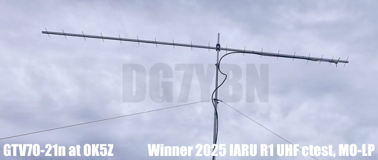
GTV 70-21n Yagi 'Voskhod' with bent Driven Element
EME + SSB narrow bandwidth version ... strictly G/T breeding
This Yagi has very low back lobes for its length. It may serve as single antenna for portable
use and certainly make a useful 4 x vertical stack. It makes a quiet contest antenna due to its
high F/B. The bent DE (K6STI style) transforms from approx. 17 ohms to 50 ohms at feed point.
It is another Yagi that needs to be built in a very accurate way. Date of issuing this design : 22nd of Aug. 2019

Plotted Return Loss
About the naming:
With spacecraft Voskhod 2 the first spacewalk of mankind was achieved:


As I understand it, re-entering the capsule was a tight affair but
nevertheless it was the first time a human was out in space.
• Here is a link to a documentation about Leonov and the spacewalk mission by the British BBC:
https://www.bbc.co.uk/news/magazine-29534966
Current distribution


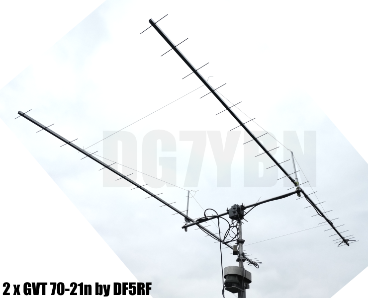
2 x GTV 70-21n built by Gernot, DF5RF
GTV 70-21n built by Thomas, M0ABA


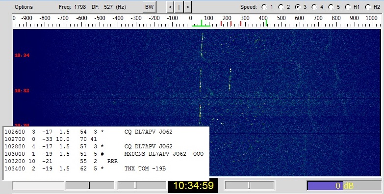
And a quick first EME QSO dated 2019-09-01: MX0CNS < > DL7APV with no good Farady Rotation
Performance Data
Specs: with 4 mm elements @ 432.1 MHz
Gain vs. isotr. Rad.  18.2 dBi
Gain vs. Dipole       16.1 dBD
-3 dB E-plane         23.8 deg.
-3 dB H-plane         24.6 deg.
F/B                  -40.5 dB
F/R                  -32.4 dB
Impedance               50 ohms
Mechan. Length        4775 mm incl. 2 x 40 mm stand off
Electr. Length        6.77 λ

VSWR Bandwidth        1:1.48 (as in VE7BQH Antenna Table)

Stacking dist. h-pol.
top-to-bottom         1.63 m or 5.34 ft
side-by-side          1.68 m or 5.52 ft
How many OMs have been looking up this design?
Geometry
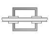
Table 2: GTV 70-21n, 4 mm elements through boom:
"Ready to saw and drill" data for mounting elements through boom with BC according SM5BSZ's BC.exe:
Note: with through Boom BC it is important to stick to the boom end offsets given below!
Metric Boom 20 x 20 x 2 mm
|
Boom shape: square Boom dim: 20 x 20 mm Wall thickn.: 2.0 mm Holes in boom: 6.0 mm Offset rear: 40 mm Offset front: 40 mm |
|

Note: with through Boom BC it is important to stick to the boom end offsets given below!

Metric Boom 25 x 25 x 2 mm
|
Boom shape: square Boom dim: 25 x 25 mm Wall thickn.: 2.0 mm Holes in boom: 6.0 mm Offset rear: 40 mm Offset front: 40 mm |
|
Note: with through Boom BC it is important to stick to the boom end offsets given below!

Imperial Boom 1", elements 4.00 mm
|
Boom shape: square Boom dim: 1 x 1 inch Wall thickn.: 1.6 mm Holes in boom: 6.0 mm Offset rear: 40 mm Offset front: 40 mm |
|
Note: All the above include a "Segmentation Density Correction" (SBC) of 1.1 mm plus an offset of 0.70 mm per element = 1.8 mm
for compensation of the insulators (7arrays.com
Note: with through Boom BC it is important to stick to the boom end offsets given below!
Read abt. the SBC here

Imperial Boom 1", elements 3/16 inch
|
Boom shape: square Boom dim: 1 x 1 inch Wall thickn.: 1.6 mm Holes in boom: 7.9 mm Offset rear: 40 mm Offset front: 40 mm |
|

Note: All the above include a "Segmentation Density Correction" (SBC) of 1.1 mm plus an offset of 0.70 mm per element = 1.8 mm
for compensation of the insulators as shown above in combination with SM5BSZ'S BC.exe values.
Note: with through Boom BC it is important to stick to the boom end offsets given below!
Read abt. the SBC here
For making of a 'Blade Dipole'
Sketch of Bent Dipole

Radiation Pattern and VSWR Plots
Elevation and Azimuth plot at 432.1 MHz (4 mm ele.)


SWR and Return Loss plots - simulated with 4nec2
(I have settled the best Retrun Loss a bit higher for giving headroom in wet weather)

This Yagis S11: Return Loss (dB) 400 ... 450 MHz plotted by ZS6JON with an Anritsu MS2000 VNA:


Stacking
As on 432 MHz the Y-factor = T_earth / T_sky is so high, I see little chances to
improve an array's RX performance by using "Over Stacking" distances. However, depending on
the level of local QRM it might be worthwhile to try a decreased distance, especially in the H-plane.
Stacking Dist.    DL6WU Formula
H-plane               1.68 m
E-plane               1.63 m
A 4 Yagi bay
Elev. Plot

Azim. Plot

Gain vs. isotr. Rad.  24.1 dBi
Gain vs. Dipole       22.0 dBD
-3 dB H-plane, appr.  17.4 deg.
-3 dB E-plane, appr.  12.0 deg.
F/B                  -44.8 dB
F/R                  -33.1 dB
T_ant                 52.7 K*
G/T                   6.89 dB*

at Tsky = 27 K, Tearth = 1800 K as in newer VE7BQH Antenna Table
3D pattern plot with 4nec2's 3D viewer

Antenna G/T with AGTC lite:

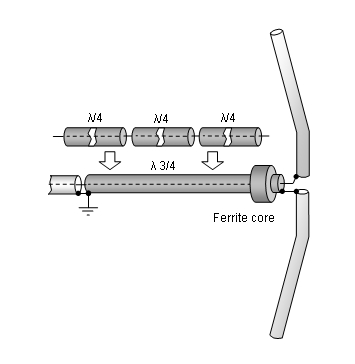
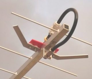
Symmetrising 50 to 50 ohms feedline to 432 MHz Bent DE
The principle is similar to the 1/4 Lambda coax. Adding 2 x 1/4 Lambda or a half wave line does not change anything but allows
to form a gentle bow below the boom or until behind the Reflector. Follow practical construction hints on "Building a Yagi" page.
 Attenzione!
Take care when lengthening the coax, measure the actual electrical length instead of considering v-factors specified in a catalogue only.
Attenzione!
Take care when lengthening the coax, measure the actual electrical length instead of considering v-factors specified in a catalogue only.A good choice may be the diam. 5 mm PTFE coax RG-142 B/U: real resonate length (432.2 MHz as 3/4 Lambda) shield-shield is around 348 mm
 Find more information on Phasing & Matching Lines page
 73, Hartmut, DG7YBN