-
• Main Page
- • Home • Building
-
- Boom CorrectionIntro to Boom Correction and complete Collection of Factors
• DL6WU / G3SEK formulas and charts in detail
• DJ9BV insulated through boom
• I0JXX insulated through boom
• K1FO insulated through boom
• VE7BQH Cushcraft & Cudee on Boom
• DG7YBN semi-insulated on Boom
• Intro to SM5BSZ's BC.exe
• Segmentation Issues and more ... - Symm. & BalunsSymmetrising Devices from Sleeve Balun, F9FT Tube, EMI, G0KSC, Pawsey, 50 ohms Quarter Wave Line to 12.5 and 28 ohms DK7ZB Match ... plus Test Equipment - the RF Current Meter
- Phasing & Matching LinesHow to measure coax stub lines, produce coaxial impedance transformation lines, Baluns and how to stack and match with coax lines
- Howto - Bent DEHow to bent a GTV Yagi DE with a simple selfmade tool:
Bending aluminium tubes by hand leads to buckles and brocken tubes. So I show what a simple selfmade tool looks like. You will need just a piece of wood, a few minutes and a jigsaw to produce one.
It will make the job much easier.
DIY - Bending Tool
- Building a YagiA collection of building hints - from DE-Box to bending Support Struts and mounting Elements.
- Boom StrutsA collection of building hints - Planning and bending Support Struts and making bending tools.
- Basic MechanicsAn introduction to mechanics with a focus on antenna systems
- Scaling Yagi ElementsHow to scale complet Yagis in Frequency and Element diameters from one dimension to another by hand
- Boom Correction
Some Antenna, Array Frame and Pole mechanics
I was to realise that quite a number of builders of Yagis seek advise how to make details
or set up their H-frame construction right regarding mechanical issues as stress.
Basic Mechanics
Framework
Lightweight Constructions
Construction Hints
A key to lightweight construction is to have all areas to be able to flex and bend under gale winds
almost similar. Which enables action, bending, stress in material to be almost evenly distibuted,
rather than piling up locally.
Disclaimer
The mechanics and formulars displayed do not intended to act according official rules or standards such as EN, ISO,
ANSI. They are general basics with no lability for any serious statics. Nor do I grant these to be right. Errecting works
according to what you see below is on your own responsibility.
Basic Mechanics
Axial Force & Normal Stress
Forces appear on bout sides of the cutting surfaces, but with opposite signs. 'Stitching the imagined
cut back together + F and -F vanish, which correlates to reality, as the beam just statictly hangs in
its bearing and does not move about.
Stress σ ('Sigma') = Force F by Area A

Given we have an aluminum tube from AW6061 T6,
with the material property Yield Stress (Rp) = 240 N/mm2
and dimension 60 x 5 mm,
... what axial force load can it take?
Now, what axial load in Newton or kg (in earths gravity field) could our tube hold for maximum?

is that a middle class car could be hanging on a M6 screw.
Note that this of coarse is without any dynamic force applied. With the car lifted very
gently. If a rapid throw adds to the factor of gravity g by 4 ... the maximum load is 1/4 now.
Stress–Strain Curve

Like a spring. An unlikly idea for metals? Not at all! Steel, aluminium and infact most
metals do show an elastic behaviour. Only much less lengthening at much higher forces
then we are used to with ordinary springs.
The odd question is why the chart line folds back from the point of max. strength to the rupture point?
This is due to a constriction of the cross section before breaking with most metals.
Hooke's Law (Robert Hooke, anno 1678) and Youngs Modulus 'E' aka 'Modulus of Elasticity' (Normal Stress)
with ε ('Epsilon') being the elongation (lengthening or shortening) of the bar

Cantilever - Load and Stress Profiles
This may be a pole fixed in the ground, or likewise screwed to some outrigger in a H-frame.
What forces and moments will base point and lower end of tube have to stand?
The mounting point is loaded with moment M l caused by the force of the windload (-)F then.
While the pole tube itself is loaded with F by x1 at any point x along its extent.
Derivation of formulas
Conditions of Equilibrium
If not so we rather have a dynamic something and the pole goes astray ...
Applied force by the wind load of the antenna and bearing reaction of the poles fastening
point do match, as long as it is not knocked over (1st equation).

Which we isolate on one side of the equation (3rd equation) and yield the resulting moment at
the fixing point finally.
Any moment as function of distance x from the applied force, down the pole so to speak
is the product of F by x1.
Section Modulus
Section Modulus is interwoven with the axioms reprensented by Hooke's Law and the Conditions of Equilibrium.
Its unit is (mm3) for we look at a cross section that shall not alter its shape under strain. With would by
acceleration. Which adds the mm to the mm2 of the looked at area.
We are looking at the Polar Section Modulus (meaning 90 degr. to the axis) here.
round solid beams, hollow shafts or technical profiles. There are plenty of table books or websites showing
more Section Moduli for other profiles.
A sample calculation without wind load on the pole tube

wind load and safety factors on the pole materials maximum strain. For that look up national regulations like
the German DIN 4131 "Antennentragwerke aus Stahl" and EN 1999 'Design of aluminium structures' to name a few.
Buckling Resistance

The K factor shows the ratio of equivalent lengths, the smaller the K the more endurable the beam.
Euler split the buckling resistance challenge into 4 cases, differing in the way the beams ends are fixed.
1. For both ends pinned K = 1.0
2. For both ends fixed, K = 0.5
3. For one end fixed and the other end pinned, K = approx. 0.7
4. For one end fixed and the other end free to move laterally, K = 2.0
(the above as in Wikipedia)
Shear Stress
Shear Stress is written as notation Τ (Greek: 'Tau')
So, Τ takes over from σ while all other stay the same.
The equation still shows Force by Area, only this time it is Shear Force instead of axial or polar force.
With is only very coarsly, actually note the index 'avg': this is the average stress through the area of the bolt.
The maximum stress occuring is much higher. With is the cause of crack and failure then.
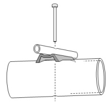
Notching Effect
A notched beam under tensile force load, lines of force are concentrated by the notch
than in the rest of the cross section. And quickly reaching the ultimate tensile strength or
even beyond that, causing immediate failure but at least a shortened life cycle.

What happens if we drill holes through a square boom?
This number much depends on the ratio a/d and the shape of the beam ie. boom.
For a round boom of a diameter D containing a transverse round hole of Ø d with
a ratio of d/D of 0.24 for 25 x 3 mm boom with a 6 mm hole we find an α= approx. 2.1.
Now all those numbers do not look encouraging. But ... they are valid for 'empty' holes.
When bolstering the bore hole with insulator and element the flow of force lines is not
canceled out completely around the hole any more. So that the Notch Factor number decreases
by large amounts for any press fit, hard enough introduced material.
So that the Notch Factor α should drop to approx. 1.5 depending on the hardness
and fit of the 'stuffing'. However, what remains is the decrease in cross section area
of the boom itself, and hence σ_max being less than without the hole(s).
In consequence builders of antennas with elements mounted through boom be advised to seek
smallest bore holes as possible constructions. A 6 mm hole through a 20 x 20 mm boom works out,
an 8 mm hole through a 25 mm boom to, with elements pressed in. But something like a 12 mm hole
through a 20 mm boom is likely to be weakening the construction substantially.
This website has been viewed how many times?
Framework
Principle of Triangulation
The diagonal tie can be a steel rope even, as it will only be loaded with drag (tensile force).
Advanced Trangulation
both diagonals (A) or a stiff member (B). With will be charged with buckling stress if force is
aplied from the right side, pushing to the left in example (B). Adding a second stiff diagonal
member will leave it to tensile stress for either diagonal member (C).
A Reinforced Traverse

an added 3rd dimension that also increases the ability to deal with sidewise applied forces.
A Reinforced H-Frame
Adding a 3rd Dimension: A Reinforced Traverse

or whatever forces are applied from aside.
Mind: This will not work it the reinforement guy wires are on the lower side.
For that we will need to add stiff members, tubes or alike with a good measure of
buckling resistance.
Lightweight Constructions
Lightweight Construction Index Numbers
In order to sense the best shape and materials for alightweight construction to be carried out,
engineers have created Lightweight Construction Index Numbers. Franky they reflect the
ratio of dead-weight load of the construction itself and the load or force it can bear.
Lightweight Construction Index Numbers LCI / Tensile Load
                    Density      Yield Stress        LCI

mild steel           7.85         235-355           3-4.8
AlCuMg1 F38          2.70         240                9
Titanim              4.4         1100                25
Glass Fibre Resin    1.9x         800          appr. 40
Carbon Fibre Resin   1.4          1600        appr. 110
Lightweight Construction Index Numbers LCI / Bending Stress
                    Density      Yield Stress        LCI

mild steel           7.85         235-355           50-75
AlCuMg1 F38          2.70         240               150
Glass Fibre Resin    1.9x         800         appr. 700
Lightweight Construction Index Numbers LCI / Buckling Stress
                    Density      Yield Stress        LCI

mild steel           7.85         235-355           1.5-2
AlCuMg1 F38          2.70         240               1.8
Glass Fibre Resin    1.9x         800         appr. 7.5
Mechanical Properties of some Materials
Mechanical Properties of Aluminium, Glass Firber Tubes and Carbon Fibre Tubes
                     Tensile Yield Strength    Ultimate Tensile Strength    Modulus of Elasticity         Density
EN AW-6061 T4:       180-235 m/mm2 = 145 MPa          241 MPa              70,000 N/mm2 = 68.9 GPa      2700 kg/m3 = 2.7 g/cc
EN AW-6061 T6              276 MPa                    310 MPa                      68.9 GPa

GFK tube (x):         200-400 MPa longitudinal
                      30-120 MPa cross sectional                                                          density = 1,6-2,0

EN AW-6061 T4 & T6 = AlMg1SiCu    0.8-1.2 % Mg, 0.4-0.8 % Si,
(x) GFK tube (50-75% fibres/weight)
Construction Hints
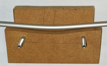
Connecting slide in tubes
A key to lightweight construction is to have all areas to be able to flex and bend under gale winds
almost similar. Which enables action, bending, stress in material to be almost evenly distibuted,
rather than piling up locally.
Joining tubes of different diameter / Aluminium & Fiber Glass tubes

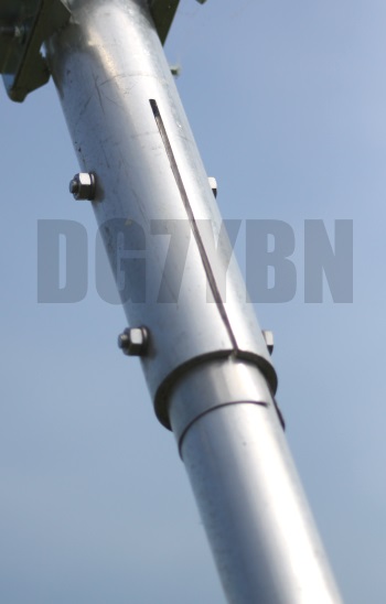
Then the stick in length is 4.5 x 60 = 270 mm
While the length of the slot is 3 x 60 = 180 mm.
Q: What is the slot for?
A: we weaken the without stiffer 60 mm tube at the stretch it is reinforced by the stuck in 50 mm tube. Q: Why so?
A: because in doing so we yield an about even distribution of stiffness over length through the joint passage
Graphical explanation:
On left: tube just slided in, tight fit, stiffens the mid section against the rest, uneven bending deformation line
Mid: outer tubes 'slide in section' weakend in constructive way, almost even bending deformation
on right: ideal bending line, even spread deformation -> even spread stress
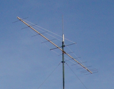
A Storm Supension for a Yagi Boom
Long Yagis tend to swing and vibrate in gale winds. Because the free boom ends can be pushed either side
by the force of the wind. Adding stability by increasing the booms cross sectional diameter is one way
of dealing with this issue.
However a far more effective methode is to add a dimensional stabilty
if possible the way the antenna is mounted. A 'triangulated' rope suspension adds a left / right dimension to the
thin boom tube. Which because of its dimension can potentially add way more strength to the boom & strut
construction than say doubling the booms thickness can.
• Use quality ropes or guy wires that provide little to nill lengthening.
Sailing shops hold very good wire ropes with Kevlar, Dyneema (R), aramid or polyester guy rope or other cores
that provide strength and lenghtening close to steel wires at thin diameters.
• An important detail is how to attach wires at far boom ends; do not drill large holes through the boom
here. Or fit reinforcenment plates if you do so. We do not want to weaken the boom tube locally,
especially not at a point where we lead forces into it.
• Fixing points shall be far way from element positions to ensure least influence on the electrical properties
of the Yagi-Uda. That typically is in the mid point between two elements.
Photo of an example here with the almost 7 m long 144 MHz UR5EAZ RS2-12 element Yagi.
It is built on a plastic lace of 24 x 28 mm as boom ...
Gusset Plates for an Arrays H-frame

Line of force in their distance to one another resemble stress. The more locally condensed,
the more local stress is applied.
(A) The lines of force are concentrated in the sharp corner angle
(B) With the gusset plate the lines of force can run through the plate

Tapered H-frame and bending moments
Enlarging the diameters with increasing bending moment enables to set up lightweight but
strong frames. The key to best ratio of weight to capacity is to increase the tube diameters
proportional to the bending moment. Which works out by carefully chosing tubes with the right
Section Modulus per piece and position.
73, Hartmut, DG7YBN