-
• Main Page
- • Home
• Antennas - • 432 MHz
- YBN 70-5mA 0.5 m 432 MHz blue print of the YBN 2-5m 50 ohms high F/B direct feed 144 MHz Low Noise Yagi
3D Plot
- YBN 70-8zA 1.5 m high gain 28 ohms Yagi.
A design partly based on the hardware of the WY-7010, turning it into a 8 ele. 28 ohms Yagi with cleaner pattern, +1.8 dB gain and better VSWR.
Azimuth Plot
- YBN 70-14wzTune up your 19 ele. Tonna!
A design based on the hardware of the F9FT, turning it into a 14 ele. OWL with cleaner pattern, +0.3 dB gain and SWR less than 1.2 from 430 to 440 MHz
Azimuth Plot
- YBN 70-14+4wA 3.2 m very wideband 50 ohms Yagi with reflector wall that covers the whole 70 cm band with ease
Elevation Plot
- GTV 70-2wA 0.14 m GTV useful for portable operation and up to the satellit band and handheld activities of any kind
Elevation Plot
- GTV 70-3wA 0.21 m GTV useful for portable operation and up to the satellit band and lower noise stacks of any kind
Elevation Plot
- GTV 70-4wA 0.33 m wideband GTV useful for portable operation up to the satellit band and lower noise stacks of any kind
Elevation Plot
- GTV 70-4mA 0.34 m GTV useful for portable operation up to the satellit band and lower noise stacks of any kind
Elevation Plot
- GTV 70-6mA 0.79 m GTV useful for portable operation and lower noise stacks of any kind
Elevation Plot
- GTV 70-7wA 0.96 m GTV useful for portable operation up to the satellit band and lower noise stacks of any kind
Elevation Plot
- GTV 70-7nA 1.1 m 432 MHz blue print of the low impedance, yet 50 ohms direct feed 144 MHz Low Noise Yagi introduced in Dubus 1/2013
Elevation Plot
- GTV 70-8nA 1.3 m 432 MHz GTV with high gain but low backlobe volume. Makes a very compact 4 Yagi bay for QRP EME or contesting.
Elevation Plot

- GTV 70-9wA 1.44 m GTV ment to be useful as a vertical stack for contesting or be an ideal small size portable Yagi
Elevation Plot
- GTV 70-10wA 1.63 m GTV useful for portable operation up to the satellit band and lower noise stacks of any kind
Elevation Plot
- GTV 70-11wA 2.01 m GTV ment to be useful as a vertical stack for contesting or be an ideal small size portable Yagi or minimum size EME 4 bay
Elevation Plot
- GTV 70-13mA 2.5 m GTV ment to be useful as a vertical stack for contesting or be an ideal small size portable Yagi or minimum size EME 4 bay
Elevation Plot
- GTV 70-14m2.9 m version of the low impedance, yet 50 ohms direct feed Low Noise Yagi with bent DE introduced in Dubus 1/2013
Elevation Plot
- GTV 70-17m3.7 m version of the low impedance, yet 50 ohms direct feed Low Noise Yagi with bent DE introduced in Dubus 1/2013
Elevation Plot
- GTV 70-18w4.0 m version of the low impedance, yet 50 ohms direct feed Low Noise Yagi with bent DE introduced in Dubus 1/2013
Elevation Plot
- GTV 70-19m4.2 m version of the low impedance, yet 50 ohms direct feed Low Noise Yagi with bent DE introduced in Dubus 1/2013
Elevation Plot
- GTV 70-21n4.7 m version of the low impedance, yet 50 ohms direct feed Low Noise Yagi with bent DE introduced in Dubus 1/2013
Elevation Plot
- GTV 70-23m5.3 m version of the low impedance, yet 50 ohms direct feed Low Noise Yagi with bent DE introduced in Dubus 1/2013
Elevation Plot
- GTV 70-25m5.9 m version of the low impedance, yet 50 ohms direct feed Low Noise Yagi with bent DE introduced in Dubus 1/2013
Elevation Plot
- GTV 70-30m7.3 m version of the low impedance, yet 50 ohms direct feed Low Noise Yagi with bent DE introduced in Dubus 1/2013
Elevation Plot
- GTV 70-34w8.5 m version of the low impedance, yet 50 ohms direct feed Low Noise Yagi with bent DE introduced in Dubus 1/2013
Elevation Plot
- GTV 70-46w12.0 m version of the low impedance, yet 50 ohms direct feed Low Noise Yagi with bent DE introduced in Dubus 1/2013
Elevation Plot
- DL6WU YagisThe DL6WU Longyagi Series
Sample plot: 32 el. plus 4 x reflector
Elevation Plot

- YBN 70-5m
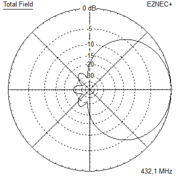
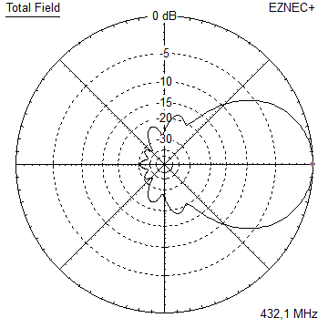
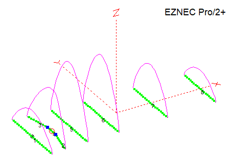
GTV 70-6m Yagi with bent Driven Element
This Yagi shows quite a low Antenna Temperature and a moderate gain for its length, which altogether leads to a good G/T number.
The shape of the rear lobes perdestines it for larger vertical stacks.
It may serve as a contest stack or post stamp size QRPP EME 4-Yagi-Bay. This Yagi is the scaled version of the GTV 2-6m.
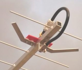
The bent DE (K6STI style) transforms to 50 ohms at feed point for direct feed. Design date of issue: 2025.10.26 .
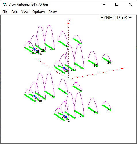
Current distribution
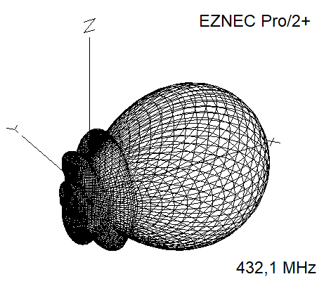
Performance Data
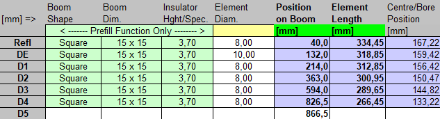
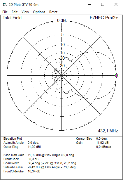
Specs: with 8 mm elements @ 432.1 MHz
Gain vs. isotr. Rad.  11.9 dBi
Gain vs. Dipole        9.8 dBD
-3 dB E-plane         46.4 deg.
-3 dB H-plane         56.2 deg.
F/B                  -30.3 dB
F/R                  -22.8 dB
Impedance               50 ohms
Mechan. Length        866 mm incl. 2 x 40 mm stand off
Electr. Length        1.13 λ

Stacking dist. h-pol. (100 percent per DL6WU)
top-to-bottom         0.737 m or 2.42 ft
side-by-side          0.881 m or 2.89 ft
How many OMs have been looking up this design since Oct. 2025?
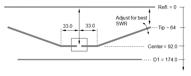
Geometry
Bent Dipole: DE(a) is the inner straight length and pos. on boom, DE(b) is position of tips and span width when bent
|
• Drawing of the blade dipole as PDF, • The Dipole of the GTV 70-9w fits the GTV 70-10w nicely (tnx Thomas, M0ABA for measuring this!) |
|

The model uses EZNEC's Auto-Segmentation at 1050 MHz.
The DE's is 10 mm for all examples.
Using a 'Blade Dipole' is recommended with elements through boom
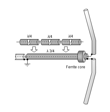
A simple symmetrising section may be made from a 3 x 1/4 Lambda line grounded at the far end with
N-flange-bushing and an aluminium plate and ferrite core added as close as possible to the DE,
see below.
This Yagi with 8 mm elements on a 15 x 15 mm boom with standard insulators
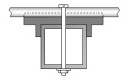
|
Ele. 8.0 mm DE 10.0 mm Boom 15 x 15 mm |
|

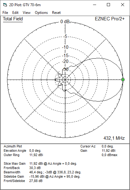
"Ready to saw and drill" data for mounting elements on boom with BC according DG7YBN for standard insulators
as sold by WiMo, Tino's Funkshop, HF-Kits NL, 7arrays:
You may alter the rear offset as long as you keep a minimum of 40 mm, it will not influence an 'on boom' BC.
Building hints:
For building hints see the GTV 70-19
For fastening elements through boom
For making of a 'Blade Dipole'
Radiation Pattern and VSWR Plots
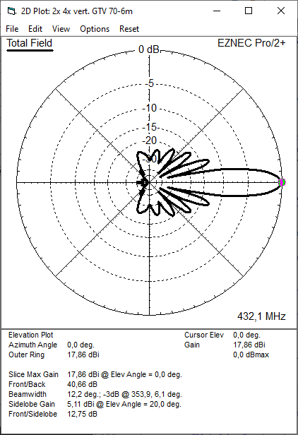
Elevation and Azimuth plot at 432.1 MHz (Elements 8 mm)
VSWR and Return Loss (S11)
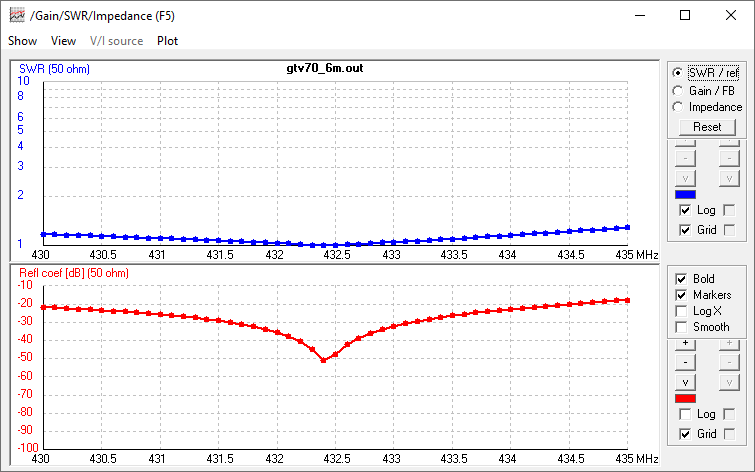
Downloads
none so far
Stacking
Stacking Dist.    DL6WU Formula
H-plane               0.737 m
E-plane               0.881 m
4 Yagi stack in H shape
Elevation and azimuth plot and data of 4 Yagi bay using DL6WU stacking distances
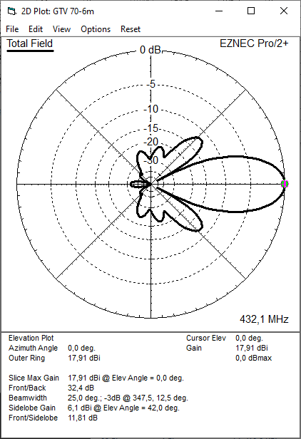

Gain vs. isotr. Rad.  17.91 dBi
Gain vs. Dipole       15.76 dBD
-3 dB H-plane         25.0 deg.
-3 dB E-plane         20.6 deg.
F/B                  -32.4 dB
F/R                  -23.4 dB
T_ant                 110.7 K*
G/T                  -2.54 dB*
Theoretical numbers - these do not include phasing line losses
nor imperfections caused by H-frames or mast poles etc.
*) T_sky = 27 K, T_earth = 1800 K as in newer VE7BQH G/T table
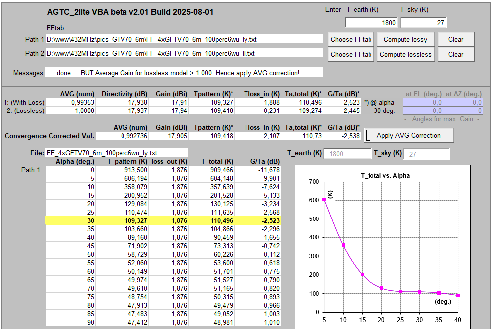
Screenshot of the Excel VBA AGTC-2lite for this 4 Yagi stack
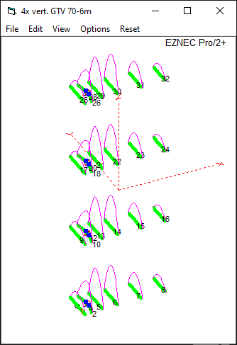
A vertical 4 Yagi stack
stacked at 733 mm: 17.9 dBi at a HPBW of 46 degr. on just 2.2 m of height on pole

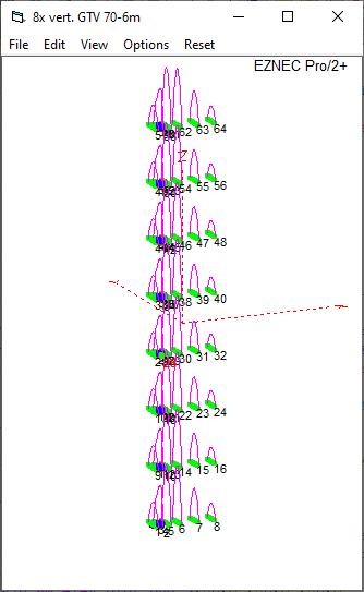
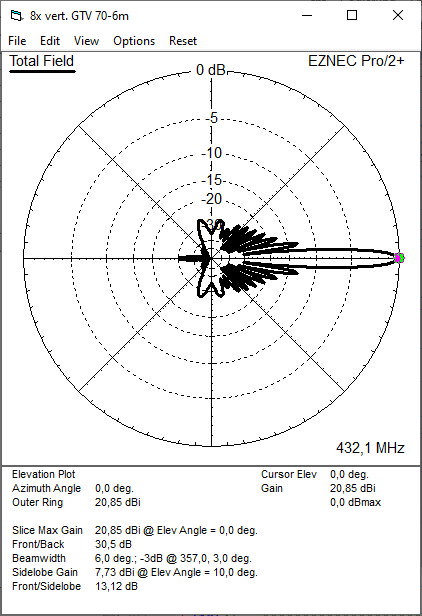
A vertical 8 Yagi stack
stacked at 733 mm: 20.9 dBi at a HPBW of 46 degr. on just 5.13 m of height on pole
A 2 x 180 deg. vertical 4 Yagi stack
stacked at 733 mm: increased F/B by optimised distance Refl. to Refl. of 725 mm
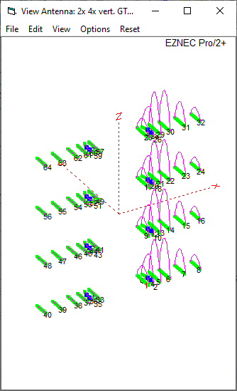
A brief description of this array of 2 x 180 deg. 4 x vert. GTV 70-6m

Symmetrising 50 to 50 ohms feedline to 432 MHz Bent DE
The principle is similar to the 1/4 Lambda coax. Adding 2 x 1/4 Lambda or a half wave line does not change anything but allows
to form a gentle bow below the boom or until behind the Reflector. Follow practical construction hints on "Building a Yagi" page.
 Attenzione!
Take care when lengthening the coax, measure the actual electrical length instead of considering v-factors specified in a catalogue only.
Attenzione!
Take care when lengthening the coax, measure the actual electrical length instead of considering v-factors specified in a catalogue only.A good choice may be the diam. 5 mm PTFE coax RG-142 B/U: real resonate length (432.2 MHz as 3/4 Lambda) shield-shield is around 348 mm
 Find more information on Phasing & Matching Lines page
 73, Hartmut, DG7YBN